I am having trouble getting an ODrive 3.6 24V (fw-v0.4.12) board up and running with a somewhat unusual motor. I measured the motor to have 16 pole pairs by energizing one phase and counting pulses, and used axis.encoder.shadow_count to measure 3,150,895 CPR. When I run AXIS_STATE_FULL_CALIBRATION_SEQUENCE, the motor rotates back and forth a bit as expected, but at the end throws the encoder error ERROR_CPR_OUT_OF_RANGE.
Configuration as it stands now:
config:
startup_motor_calibration = False (bool)
startup_encoder_index_search = False (bool)
startup_encoder_offset_calibration = False (bool)
startup_closed_loop_control = False (bool)
startup_sensorless_control = False (bool)
enable_step_dir = False (bool)
counts_per_step = 2.0 (float)
watchdog_timeout = 0.0 (float)
step_gpio_pin = 1 (int)
dir_gpio_pin = 2 (int)
calibration_lockin: …
sensorless_ramp: …
general_lockin: …
motor:
error = 0x0000 (int)
armed_state = 0 (int)
is_calibrated = True (bool)
current_meas_phB = 0.5950702428817749 (float)
current_meas_phC = 0.018635690212249756 (float)
DC_calib_phB = -0.5949123501777649 (float)
DC_calib_phC = -0.8239499926567078 (float)
phase_current_rev_gain = 0.02500000037252903 (float)
thermal_current_lim = 53.0745735168457 (float)
get_inverter_temp()
current_control: …
gate_driver: …
timing_log: …
config: …
controller:
error = 0x0000 (int)
pos_setpoint = 0.0 (float)
vel_setpoint = 0.0 (float)
vel_integrator_current = 0.0 (float)
current_setpoint = 0.0 (float)
vel_ramp_target = 0.0 (float)
vel_ramp_enable = False (bool)
config: …
set_pos_setpoint(pos_setpoint: float, vel_feed_forward: float, current_feed_forward: float)
set_vel_setpoint(vel_setpoint: float, current_feed_forward: float)
set_current_setpoint(current_setpoint: float)
move_to_pos(pos_setpoint: float)
move_incremental(displacement: float, from_goal_point: bool)
start_anticogging_calibration()
encoder:
error = 0x0000 (int)
is_ready = False (bool)
index_found = True (bool)
shadow_count = 1422975 (int)
count_in_cpr = 1422975 (int)
interpolation = 1.0 (float)
phase = 0.6731939315795898 (float)
pos_estimate = 1422975.875 (float)
pos_cpr = 1422975.875 (float)
hall_state = 0 (int)
vel_estimate = 250.00003051757812 (float)
calib_scan_response = 1346469.0 (float)
config: …
set_linear_count(count: int)
sensorless_estimator:
error = 0x0000 (int)
phase = -2.678755283355713 (float)
pll_pos = -2.947742223739624 (float)
vel_estimate = 19.048736572265625 (float)
config: …
trap_traj:
config: …
watchdog_feed()
Encoder config:
mode = 0 (int)
use_index = True (bool)
find_idx_on_lockin_only = False (bool)
pre_calibrated = False (bool)
zero_count_on_find_idx = True (bool)
cpr = 3150895 (int)
offset = 614152 (int)
offset_float = 0.6015468835830688 (float)
enable_phase_interpolation = True (bool)
bandwidth = 1000.0 (float)
calib_range = 0.10000000149011612 (float)
calib_scan_distance = 50.0 (float)
calib_scan_omega = 12.566370964050293 (float)
idx_search_unidirectional = False (bool)
ignore_illegal_hall_state = False (bool)
Per various forum suggestions, I’ve tried varying the encoder.config.calib_range, and have also futzed with parameters like .scan_distance and various motor/controller options. In some cases, I’ve been able to get the motor to respond to position or velocity commands, but it’s frustratingly unreliable; sometimes it doesn’t move, sometimes it runs at the desired RPM, sometimes it keeps moving after it stops, sometimes it buzzes, etc.
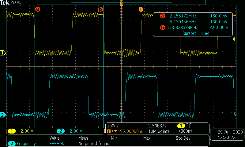
The motor uses a Renishaw integrated encoder with a differential output, so I’m using a MAX3028 to convert the signals to single-ended. I 'scoped the output of the chip on the A and B lines and the signal looks robust with fast rise/fall and no noise. Notably, when I rotate the motor by hand quickly, the pulse rate on these lines hits ~2.5 MHz.
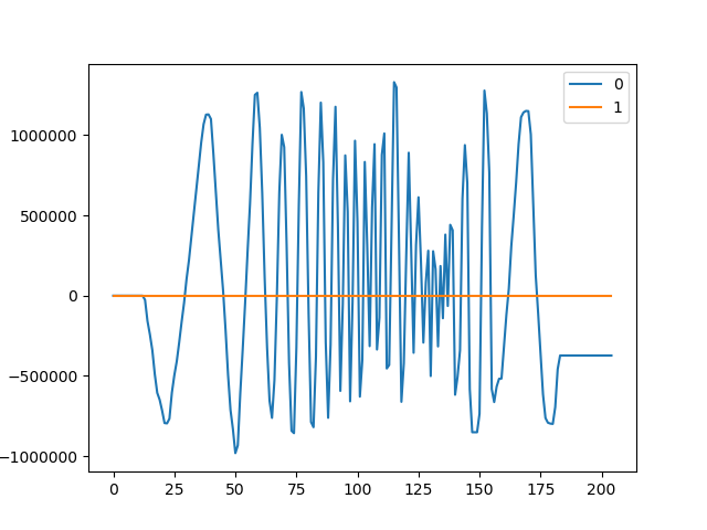
I suspect the encoder inputs aren’t keeping up with the encoder at full speed, resulting in skipped steps. I verified this by writing down axis.encoder.shadow_count and manually rotating the motor back and forth through 360 degrees (marked using the stage’s built-in degree markers). After several iterations of this I found axis.encoder.shadow_count had drifted substantially in some cases. I also tried plotting the encoder outputs using start_liveplotter(lambda:[odrv0.axis0.encoder.pos_estimate, odrv0.axis0
…: .controller.pos_setpoint]); here’s the result:
In the plot above, I kept my hand on the motor and slowly moved it back and forth through ~180 degrees a few times (the smooth part), then quite quickly through the same range (the small spikey part), then slowly again, then quickly again, then finally slowly a third time. You can see that the quick parts don’t register the full encoder range, even though I physically rotated the motor the same amount each time. On the second quick rotation run, the encoder baseline also accumulated significant errors, resulting in the third set of slow rotations being offset by a few million counts.
During one search, a thread popped up where @madcowswe suggests the encoder inputs are currently limited to 3.5 MHz, but could go up to 21 MHz if needed. Per my 'scope measurements earlier (~2.5 MHz max pulse rate), the current configuration should still work but the graphs above suggest pulses are being missed.
I did try changing the GPIO speeds from LOW to MEDIUM / HIGH / VERY HIGH, starting at line 103 of gpio.c (which shouldn’t really make a difference, since this is the index pin):
/*Configure GPIO pins : PCPin PCPin PCPin */
GPIO_InitStruct.Pin = M1_ENC_Z_Pin|GPIO_5_Pin|M0_ENC_Z_Pin;
GPIO_InitStruct.Mode = GPIO_MODE_INPUT;
GPIO_InitStruct.Pull = GPIO_NOPULL;
GPIO_InitStruct.Speed = GPIO_SPEED_FREQ_VERY_HIGH; // ZF added (previously not specified)
HAL_GPIO_Init(GPIOC, &GPIO_InitStruct);
… and starting at line 478 of tim.c:
GPIO_InitStruct.Pin = M0_ENC_A_Pin|M0_ENC_B_Pin;
GPIO_InitStruct.Mode = GPIO_MODE_AF_PP;
GPIO_InitStruct.Pull = GPIO_NOPULL;
GPIO_InitStruct.Speed = GPIO_SPEED_FREQ_VERY_HIGH; // ZF increased LOW --> High
GPIO_InitStruct.Alternate = GPIO_AF2_TIM3;
HAL_GPIO_Init(GPIOB, &GPIO_InitStruct);
I tried the same axis.encoder.shadow_count cumulative error test and it seemed to improve, but then I graphed the encoder position and saw the same issues as pictured earlier. That isn’t entirely surprising; my understanding is that the STM32F4 GPIO slew rate adjustments are only for output pins (as a way of mitigating EMI effects), rather than inputs. So that means the 3.5 MHz limitation discussed above is elsewhere in the code, but I’m not sure where.
Interested in suggestions. For what it’s worth, Thorlabs does make a dedicated controller for the stage. It’s a bit over $2k and (from what I can tell) only runs proprietary software. Ugh.