Our rover team would like to know if optical photogate sensors will work for encoding wheel position driven by a hooverboard motor.
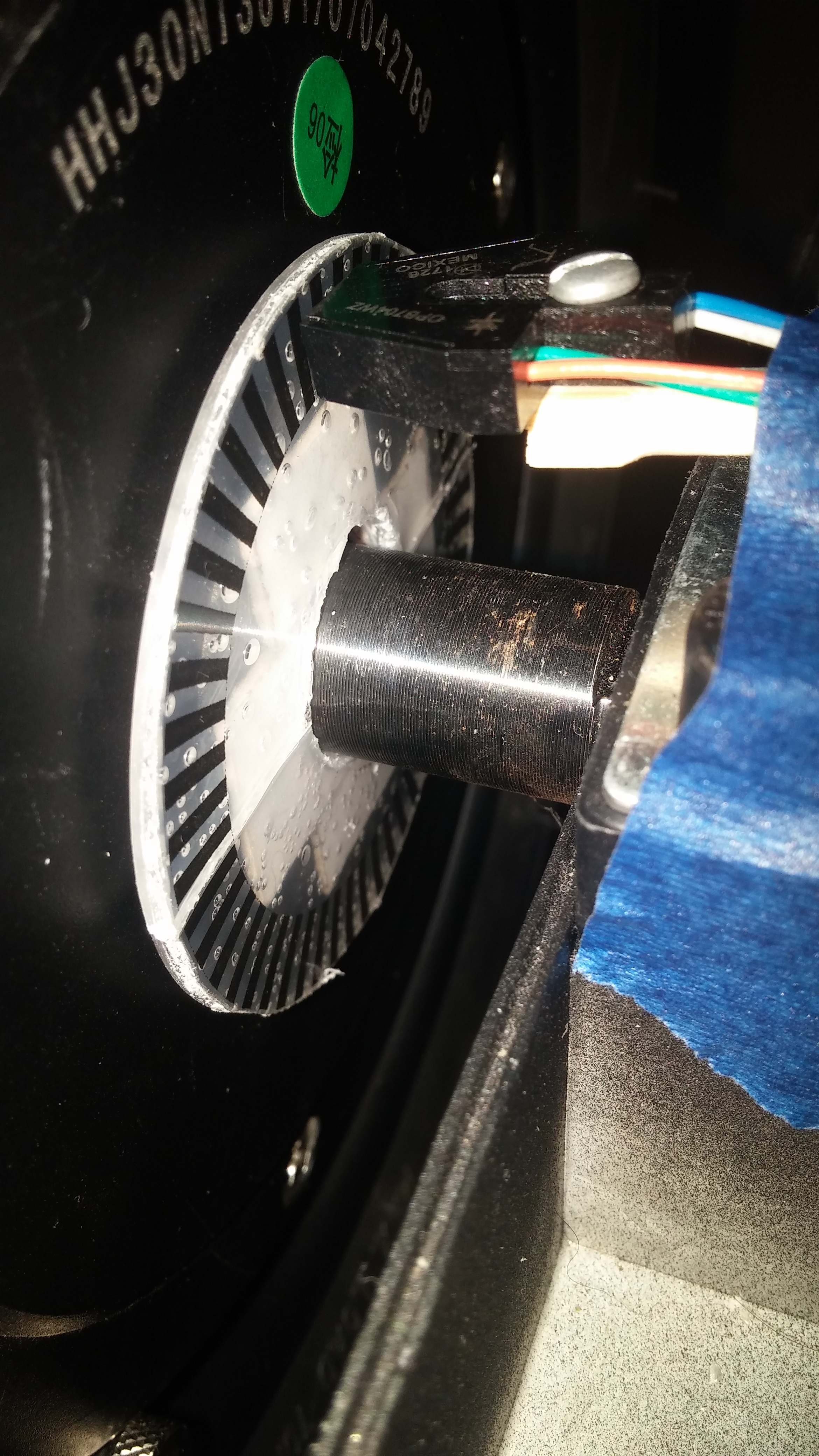
Currently a clear disk (OD 60mm) has black and clear encoder disk (50 black/50 clear segments). This disk is mounted to the inside of 10 inch wheel. Two different opb7030570 photogate sensors are detecting black to clear transitions; one black line while the other sensor see a clear line. Counters in code are tracking the number of ticks as wheel moves.
Here’s the code:
const int encoderIn = 8; // input pin for the interrupter for Rotary
const int encoderIn2 = 7; // input pin for the interrupter for Rotary2
const int statusLED = 13; // Output pin for Status indicator for LED
const int statusLED2 = 11; // Output pin for Status indicator for LED2
const int pulseOutput = 12; // Pulse output pin for external interfacing for Test
const int pulseOutput2 = 10; // Pulse output pin for external interfacing for Test
//int detectState = 0; // Variable for reading the encoder status
int val = 0; // variable for reading the encoder status
int val2 = 0; // variable2 for reading the encoder status2
int count = 0;
int count2 = 0;
int currentState = 0;
int currentState2 = 0;
int previousState = 0;
int previousState2 = 0;
void setup()
{
pinMode(encoderIn, INPUT); //Set pin 8 as input
pinMode(encoderIn2, INPUT); //Set pin 7 as input
pinMode(statusLED, OUTPUT); //Set pin 13 as output
pinMode(statusLED2, OUTPUT); //Set pin 11 as output
pinMode(pulseOutput, OUTPUT); // Set Pin 12 as output
pinMode(pulseOutput2, OUTPUT); // Set Pin 10 as output
Serial.begin(9600);
}
void loop() {
/////////Encoder 1
val = digitalRead(encoderIn); // read input value
if (val == HIGH)
{ // check if the encoder is HIGH (no rotary change)
digitalWrite(pulseOutput,HIGH); // Give a logic-High level output
digitalWrite(statusLED, HIGH); //Turn on the status LED
currentState = 1;
}
else
{
digitalWrite(statusLED, LOW); //Turn off the status LED
digitalWrite(encoderIn, LOW); // turn LED off
currentState = 0;
}
if(currentState != previousState)
{
if(currentState == 1){
count = count + 1;
Serial.print("A: ");
Serial.println(count);
}
previousState = currentState;
delay(1);
}
//////////Encoder 2
val2 = digitalRead(encoderIn2); // read input value
if (val2 == HIGH)
{ // check if the encoder is HIGH (no rotary change)
digitalWrite(pulseOutput2,HIGH); // Give a logic-High level output
digitalWrite(statusLED2, HIGH); //Turn on the status LED
currentState2 = 1;
}
else
{
digitalWrite(statusLED2, LOW); //Turn off the status LED
digitalWrite(encoderIn2, LOW); // turn LED off
currentState2 = 0;
}
if(currentState2 != previousState2)
{
if(currentState2 == 1){
count2 = count2 + 1;
Serial.print("B: ");
Serial.println(count2);
}
previousState2 = currentState2;
delay(1);
}
}
Odrive V3.5 48V board is being used. We would like to use optical encoders as the BLDC motor setup doesn’t allow for access to shaft. Would Odrive motor calibration be possible with two optical encoders and Aurdiuno code seen above? Can A, B and Z encoder inputs on Odrive controller be used with this optical setup?
Thank you kindly for your feedback and time,
John
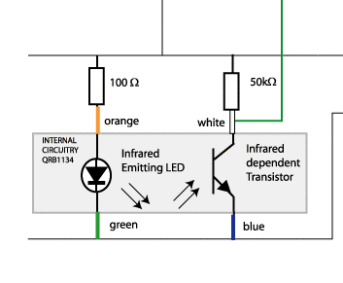
Here is the photogates used to sense the black and white transitions.
https://www.digikey.com/en/datasheets/tt-electronicsoptek-technology/tt-electronicsoptek-technologyopb70370570ahwz