Features of ODrive v3.2

So v3.2 is finally out, hooray!

As you might have seen in the blog post, here are the changes from v3.1:

  • Fix current sensor filter capacitor values
  • Break out the SPI port
  • Consolidate all 0.1" headers into two long rows
  • Remove the confusing EV (Encoder Voltage) rail.
  • Add test-points for most interesting analogue signals
  • Add precision LDO for AVCC (analog VCC)
  • Change MOSFETs to a slightly better Rdson version (30% better)
  • Adjust heatsink holes
  • Add fiducials
  • Improve labling

Which of these features (if any) is going to be of particular use to you?
Is there a feature that didn’t make it, that you would have liked to see?

Thanks for your input! ;D

2 Likes

Here are some pictures of the board btw:

Front

Back

And the source docs, including schematics, are on github here.

1 Like

Wonderful work and details so far! I really can’t wait to see this develop!

Some manufacturing perspective notes:

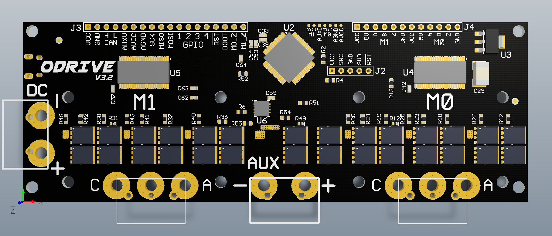
Get rid of the angle on the CPU.
The machines that would touch down a part this large, quickly, add an extra step of indexing the part fully (usually a 360 to home the nozzle) when you set anything other than a 0, 90, 180 or 270 turn. This can add tens of minutes to even a short run of boards. I understand the need for signal path length symmetry (also it looks pretty cool), but you can easily balance the signal paths with trace length instead.

Use an ENIG matte finish until you make a non-beta.
Black FR4 is fine, but stay away from glossy anything. The minor imperfections in the hermetic seal of the finished surface on a gloss FR4 board turn into nasty cracks with a lot of close-to-max thermal cycling. As we all know, crack kills.
For reasons related to oxidization, the matte surface of ENIG is essentially immune to this failure mode. It also seems to take paste better, and doesn’t need to be hand brushed for micro balls that have adhered through static when run through a wave process.
Above all, ENIG suffers abuse and mishandling the best of any PCB material. I would expect the beta board to be run through the figurative ringer.

Overall:
I would suggest you use a stack-up, CPU-under-drive design. Section each output stage into its own small board. Plan the size of each piece as a fraction of the size of a full piece of FR4 (400x400mm) to speed panelization. Assume people are going to wire it backwards, upside-down, and to their sisters cat. Making each output stage removable and thereby replaceable will go a long way to increasing the lifetime of each drive.

Use an off the shelf power stage.
For example, the Open-BLDC uses the Castle Creations power stage.

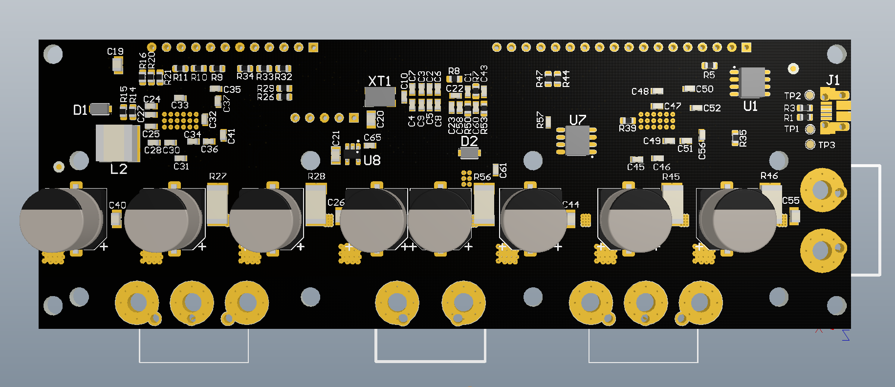
Keep the surface mount parts on one side. It is very hard to fixture for an oven, and the reflow process is nearly assured to drop any larger parts off the bottom side of the board when the paste hits liquidus and loses its surface tension. Gluing the parts down post-paste with a chipbonder is an option, but will over-inflate the cost of a low volume production.

Move the caps to the north edge of the board so the FETs can still be sinked.

Use JST or HST headers for external connections instead of 2.5mm pitch. They don’t flop around, and are much easier to solder. (They don’t ‘float’ on a wave like a 2.5 does).

Put the silkscreen for each header on both top and bottom side, and mark the first pin by thickening the edge of the border on that side so it is visible when the header is placed on top of it.

Don’t over-drill the board for fastening.
3x 10-24 0.25" long screws can develop a clamping force of over 1300lbs. More than enough to permanently mount a small board to your sisters cat.

Don’t be afraid to get close to the inside diameter tolerance for the barrels on the headers. When placed by hand or machine, a close fit keeps the header from rattling / not being seated in the barrel when it hits the lambda on the wave solder.

2 Likes

Looks great! From the perspective of what I use at my day job, handling motors in the 24V-80V range would be pretty cool. In addition, it would be very helpful if the ODrive could handle 5V-24V sensors (e.g. for homing flags) without requiring the user to add additional circuitry.

2 Likes

Wow thanks Null, so much good advice!

The angle on the CPU is mostly to look cool, there is no length matching requirements. When the time comes to do the beta launch manufacturing run I will be looking to get it done at a better price than the small batches I have been doing so far. With that, there may be some limitations with the manufacturer indeed, so I will have a word with them on how their machines handle the 45deg rotations. If it turns out there is a penalty for their machines, I’ll just stick to 90deg increments.

Yes all boards from v3.1 and ondwards have ENIG finish. Thanks for the heads up, I’ll keep it up throughout the beta too. Under what conditions do you think I should go for a cheaper finish? That is, should I keep it up for the main launch too, or try some cheaper finishes and do stress tests with that at end of beta to see if main launch can do with a cheaper finish?

Pluggable power stages is a cool idea: it would also allow a single base board and different specs power board (choose high voltage OR high current OR higher cost and get both, etc.).
The main issue I see with this is how to wire up the high current paths, which in this case is the connection to the DC bus. This needs to be able to handle ~100A, which means either the user has to solder in thick cables to every module, or we need lots of expensive connectors.
The other issue is heatsinking. The current design has all the MOSFETs lined up in a single contiguous region, so you can put a single heatsink over all of it, hence saving in cost and assembly issues.

I currently have two very large polygons going horizontal for DC+ and GND, and the phases go out vertically. It makes for a very nice horizontal/vertical matrix. Having it like this forces the bus caps to be on the opposite side of the MOSFETs, and hence I have to have a double sided board. I would have to think very hard about how to do the high current paths if I had to put the caps on the same side as the MOSFETs.

Thanks for the heads up on the JST/HST. Yes I should put silk screen on both sides, may people prefer to mount the connectors “upside down”.

The multitude of holes are for clamping down a long heatsink. I noticed that the board flexes very easily, so I was worried that if I didn’t clamp down in multiple locations, any flexing could let there be an airgap between the mosfets and the heatsink.

Yes good tip, thanks.

Overall thank you so much for all your advice, really well received!

2 Likes

Hi, I really like the project, and I can’t wait to test the v3.2 we just ordered at our lab!

We work with big humanoid robot here, and a key feature for high DoF systems could be a low power mode with QEI encoders position always updated even when the robot is off.
I think it could be easy with a small on-board battery that keeps encoder and minimal part of the STM alive when no power is present. But it may be a bit tricky when reset or flashing occurs… Maybe an other component is needed just for the absolute position recoding ?

What do you think?

1 Like

Hi @thomasfla, welcome to the ODrive community! Thank you, I’m excited for when the v3.2 are ready to ship too!

I think it is possible to keep the ODrive on in a low power state. However none of the hardware is designed to be able to have low consumption, so while the power inverters could be turned off, the board may still draw quite a lot. For example, there is no means to turn off the AUX current sense amplifier.
I guess it really depends on what is considered “low power consumption”.

I think continuously tracking the encoder while in a low power state is fairly straightforward. Tracking the encoder offset through board reset/flashing is considerably more difficult. The solution I can think of is to use an encoder on the motor that has an index (Z) line, together with an absolute encoder (like one of the AMS magnet ones) on the output side of the gearbox, to resolve the integer revolution ambiguity of the motor.

Pretty impressive list of advices !

What is the max dc voltage odrive will be able to supply to motors?

The max voltage for the ODrive is 24V DC. The max voltage on the motor depends if you mean phase voltage or line voltage. The motor kv rating (in rpm/v) is with line voltage, so I presume that is the one you are interested in?
Right now the ODrive can go up to about 80% of the DC voltage as line voltage.