Hi there,
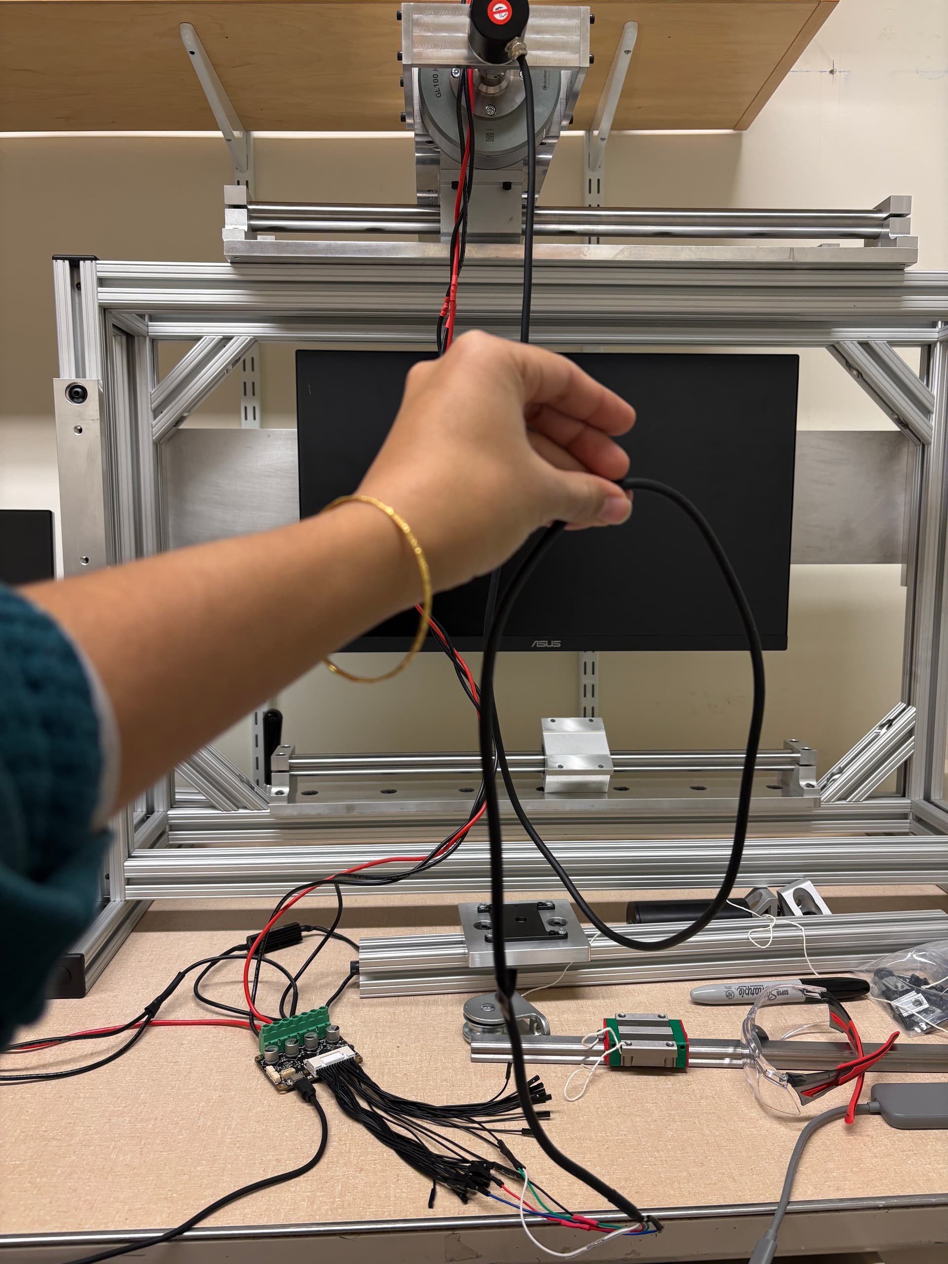
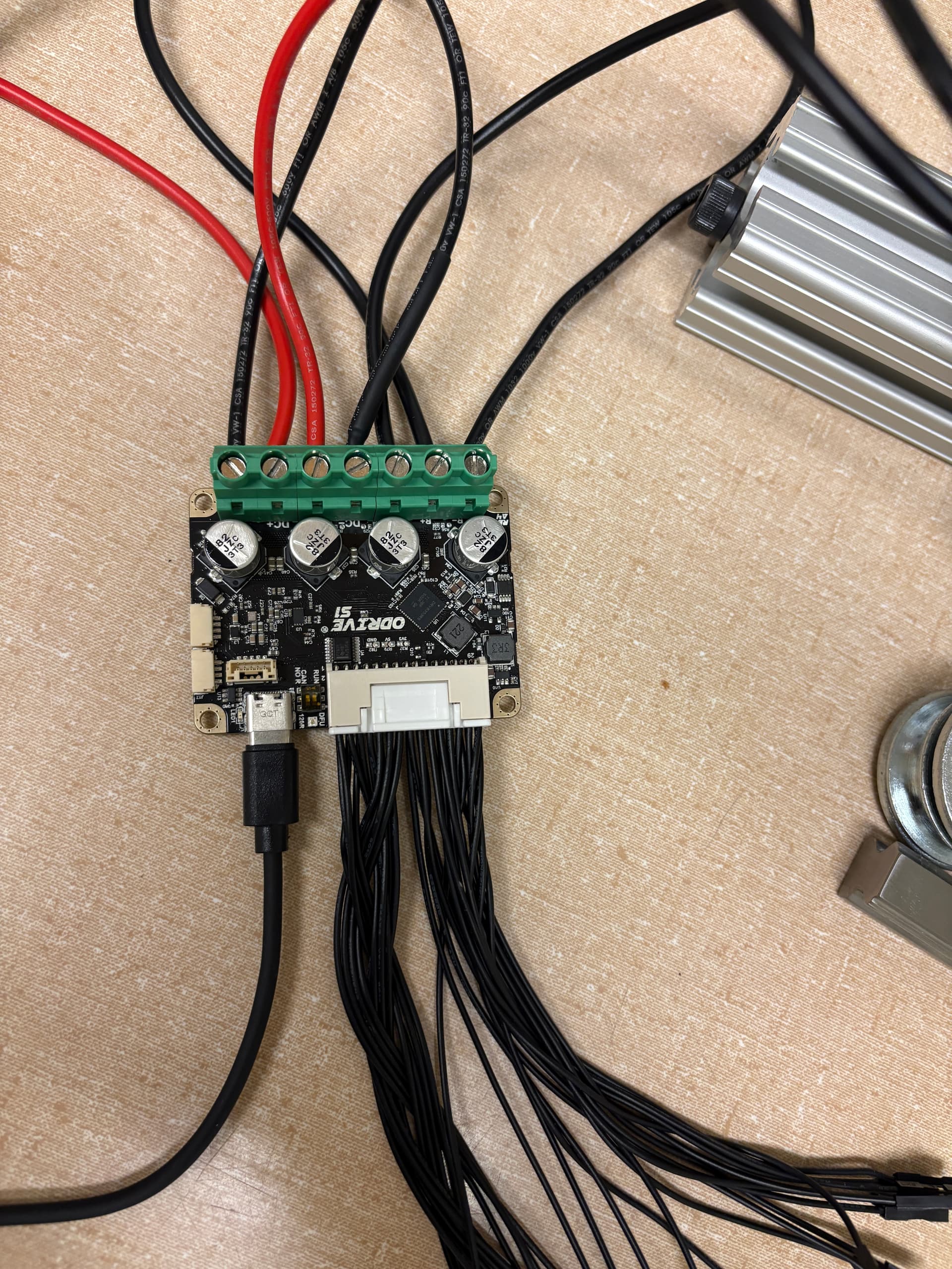
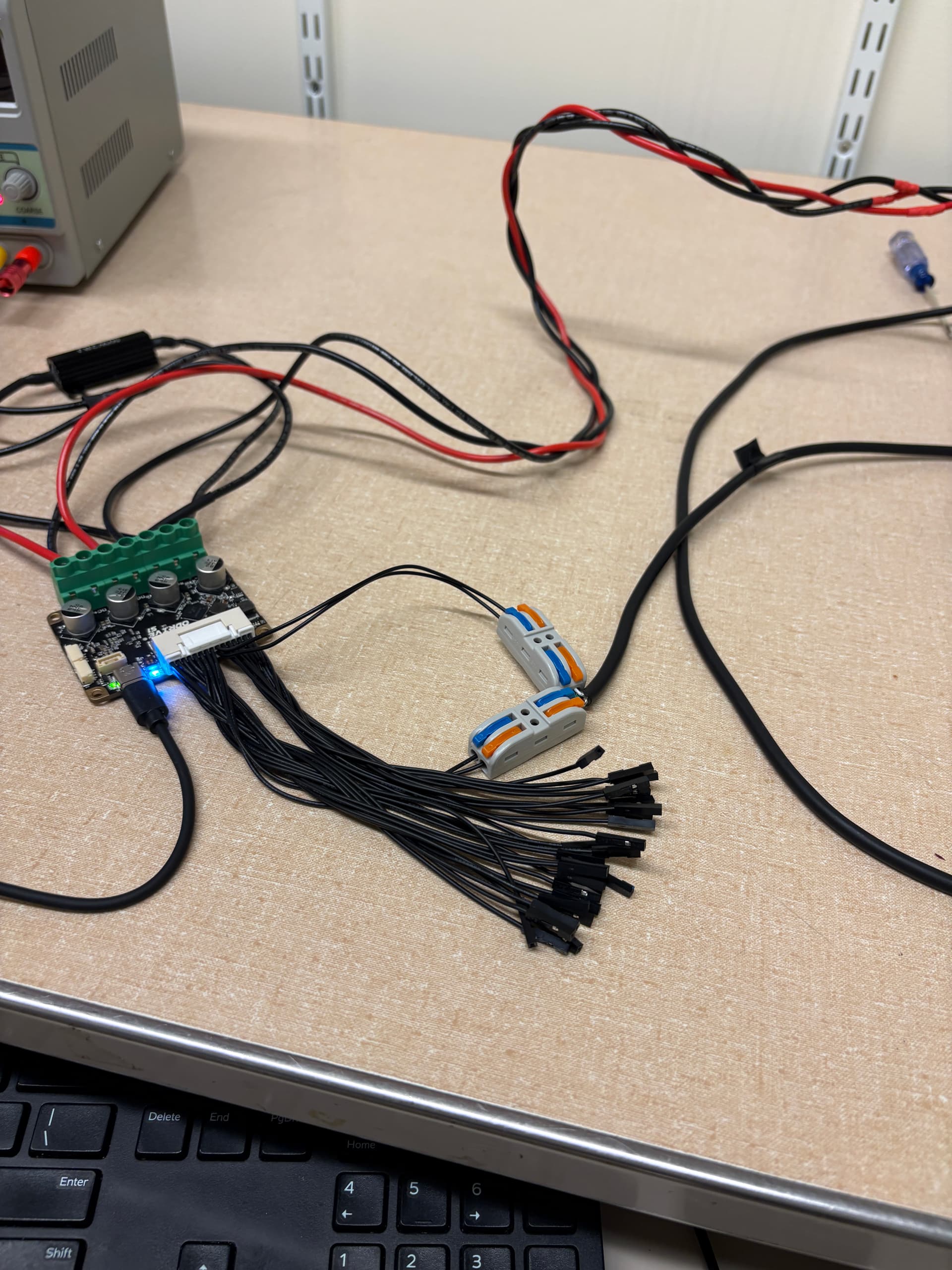
I’m using an ODrive S1 with the GL100 KV10 Gimbal motor and the 600 ppr Taiss Incremental Rotary Encoder for a human behavioral experiment. (Thank you @solomondg already for helping me order some parts a while back).
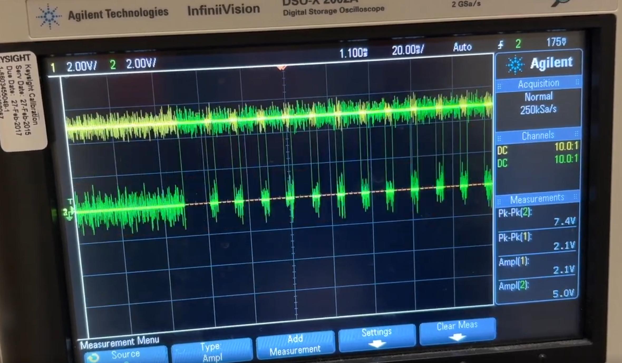
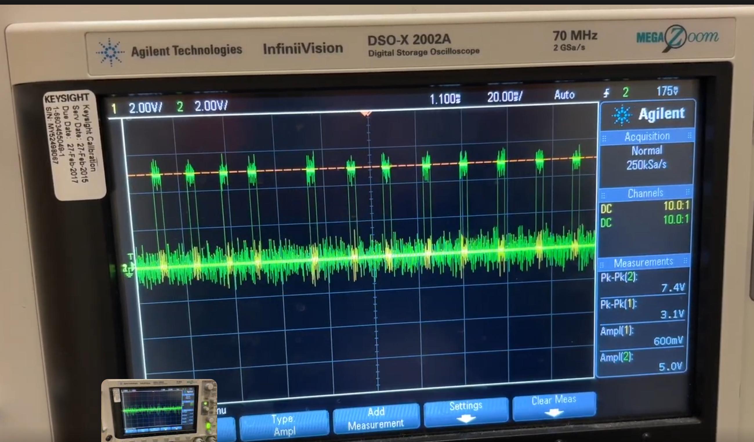
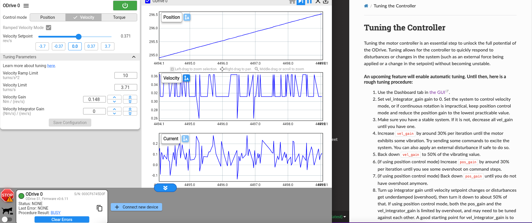
I am now trying to tune the gains of my controller using Ramped Velocity Control through the GUI. However, I’m experiencing some issues similar to this post where the velocity “dies off” to 0, and I can’t tune the controller. Furthermore, there are no errors in the GUI. Calibration completes successfully too. Following the advice from that post, I checked my rotary encoder by manually spinning the shaft, and the rotary encoder seems to work as expected (the cpr is 600*4 = 2400, and each small turn I impart on the encoder outputs about 1/2400 = 0.00042 revolutions).
Here is a google drive link to a video of the motor’s behavior during tuning. As you can see, the velocity dies to 0. The position estimates of the encoder (in blue of the Inspector) and of the motor (in green of the inspector) make sense because the motor’s position estimate is just the incremental number of revolutions spun, while the encoder’s position is the “true” fractional position of the encoder.
I had read something in the forum that the current_lim and current_calibration parameters are actually in terms of voltage for gimbal motors. Maybe my parameters are incorrect for those as I based them in terms of current. However, these posts referred to earlier firmware versions (May 2023). I’m using version 0.6.11, so I don’t know if that guidance still applies.
Do y’all have any advice on what I can do to successfully tune my motor? Below are the parameters I’ve set in the GUI:
Power Source
Power supply (DC, benchtop): 24V
DC bus overvoltage trip level: 30 V
DC bus undervoltage trip level: 10.5 V
DC max positive current: 10A
DC max negative current: -0.01A
Use brake resistor: True, 2 Ohms (I’m using the one that came with the S1)
Motor Parameters
Type: Gimbal
Phase resistance: 2.65 Ohms
Pole Pairs: 20
KV: 8.03 rpm/V NOTE: the KV listed in the motor specs is 9.3, but I changed it to 8.03 here in order to match the KT of the motor specs, which is 1.030.
Current limit: 3A
Motor calibration current: 1.8A
Motor calibration voltage: 10V
Lock-in spin current: 2.25A
Encoder Parameters
Type: ABZ encoder
Resolution: 2400
Control Mode
Control Mode: Ramped Velocity Control
Ramp limit: 10 turns/s^2
Soft velocity limit: 3.71 turns/s NOTE: the “no-load speed” according to my motor specs is 223 rpm, which is about 3.72 turns/s
Hard velocity limit: 3.71 turns/s (I made this value the same as the soft velocity limit)
Torque limit: 5 Nm
Interface
USB
Apply and Calibrate
Runs smoothly
Thank you!
Nikasha