I keep having my Odrives die on me. I think this is because of a Ground loop problem. Because I am using a CAN bus to communicate between the different ODrive’s I can’t use an Opto-Isolator because 0 is 2.5v and 1 is 5v on the High and 0v on the low wire. (I think that’s correct)
I could use a USB Opto-Isolator and then power the Teensy off the 5v coming from one of the Odrives but I’m not sure this is a good idea or if it would even solve my problem.
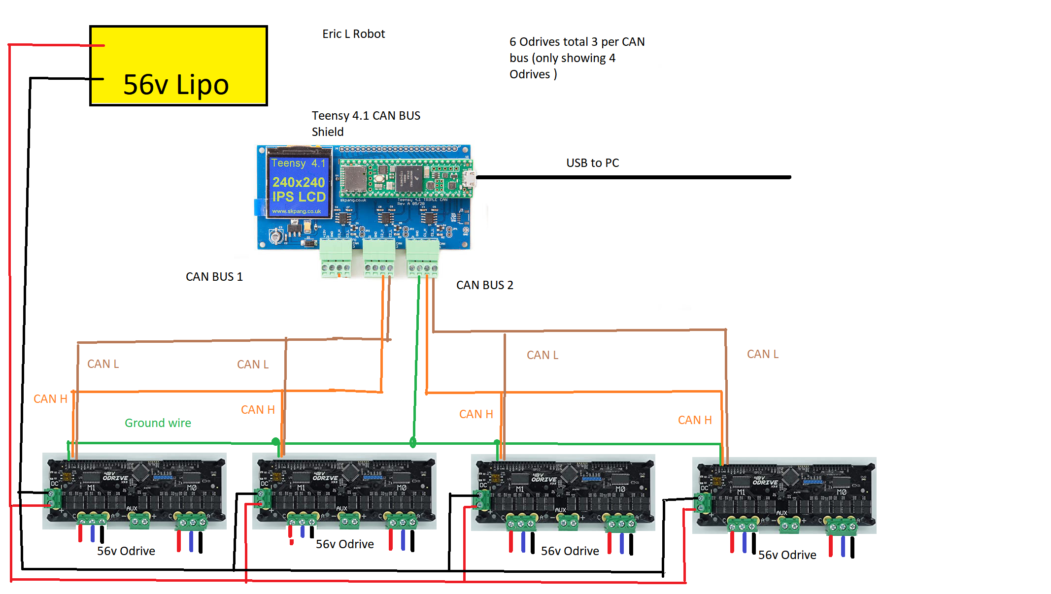
Currently, I am using a common ground like in the picture but in the past I have not connected all the grounds together and I still had the same problem.
When you say die, what exactly on the odrives died?
I am surpised that this ground loop would kill them. I would only connect one odrives ground to the Teensy ground so that there is no loop. If CAN is reliable then no point in adding more gorunds.
Do you have any inrush curent protection between the battery and the odrives?
Inrush kills. I learnt that the hard way.
I should’ve clarified this earlier. I have had the same problem on 24v and on the full 56v. I mostly test in 24v and that is where I get most of the problems with the “Odrive dying”.
When I say “dying” I should have said that the Odrive USB refuses to show up on the PC and the Odrive will not respond, sometimes I can change it to DFU mode and re-flash the firmware and then it starts working again but sometimes that doesn’t work. I am only assuming it could be a possible ground loop. I’m going to try and add a temporary resistor in series when I first power it up for 2 seconds then bypass the resistor. Maybe that may help because the problem always happens on power up.
Thanks Wetmelon for the reply
The Teensy 4.1 CAN bus shield ground is already connected to the Teensy ground and the same ground is connected to the Odrives ground as per the diagram.
I will try a USB isolator (it’s on order) and then power the teensy off of the 5v from the Odrive. (let me know if this is a bad idea)
I was unable to find a CAN isolator that would be able to output a 0v, 2.5v and 5v for a CAN bus. Correct me if I’m wrong but I thought 0 is 2.5v and 1 is 5v on the High wire and 0v on the low wire. All I can find are isolators that work on 0v or 5v.
When the CAN bus output is “ON”, the CANH line is driven to 5V and the CANL line is driven to 0V. When the outputs are off, the termination resistors allow the bus to return to ~2.5V. The drivers are 0V or 5V only
Also, 0 is the dominant bit. So when the drivers are on, there is a 0 on CANL, and the output is 0.
Hey mate. old post i know. make sure you isolate your control interface. from the odroid or you get a current feedback loop. this will be even more important if you connect to a computer. use isolated usb hub or get optical isolators for ttl signals. can get galvanicly isolated bidirectional voltage converters designed with high speed coms in mind. these are ideal to keep in the toolbox for a lot of diff projects and will solve all your troubles.
you can create that by providing the correct termination on both sides of an optically isolated interface. use two separate voltage dividers to create the 2.5v reference for each line and a driver transistor to pull one up and the other down at the same time. you should be able to drive the transistors directly with a resistor each which means your opto is high and the gate pulled low. use a comparitor between the H and L lines for sensing and drive opto directly from it. you may need to slightly separate the differential input a bit so when the voltage is floating on the bus the comparitor outputs a definite low and when the voltage is pulled to the respective buses the comparitor goes high. the same circuit works back to back and there are a few more details to fill in which definitely includes protection but essentially the interlace is simple. in total your custom opto transiver should put no less then a few kohm load across the bus to keep a relative 60ohm with all the devices connected. all except one device in the can bus should be isolated with it providing ground and power for the opto side of all of the devices. usualy this device has seperate power like a computer system or via dc-dc. all of the rest of the devices may share power with the big devices like motor controllers etc but do not connect its ground to the opticly isolated ground.