Issue: unable to calibrate the encoder due to ILLEGAL_HALL_STATE error
Setup: Odrive 3.6 24V with BLDC and Hall sensor. 22nF caps on M0A, M0B, M0Z, M1A , M1B, and M1Z all to GND.
Tests to determine issue:
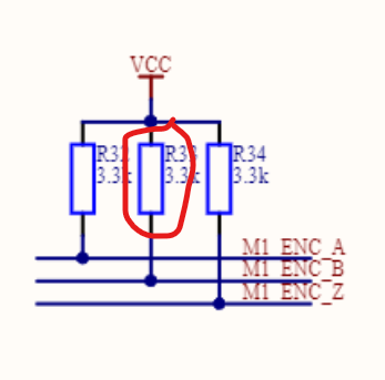
- liveplotter only shows hall_states 0, 1, 4, 5 for axis 1, and when hall_state is 0, pin M1A = 0V, pin M1B = 3.6V, pin M1Z = 0V (measured at J4 header)
- Verified both motors work correctly by flipping axis 0 and 1; axis 0 calibrated correctly both times
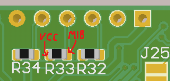
Analysis: It appears that the hall_state always reads the 2nd bit (M1B) as 0, independently of the voltage level, so I’m guessing that the board has a disconnect between the header and the micro pin. It may be the gpio pin isn’t configured correctly, but I set all the pin modes to GPIO_MODE_DIGITAL, saved, and restarted the board.
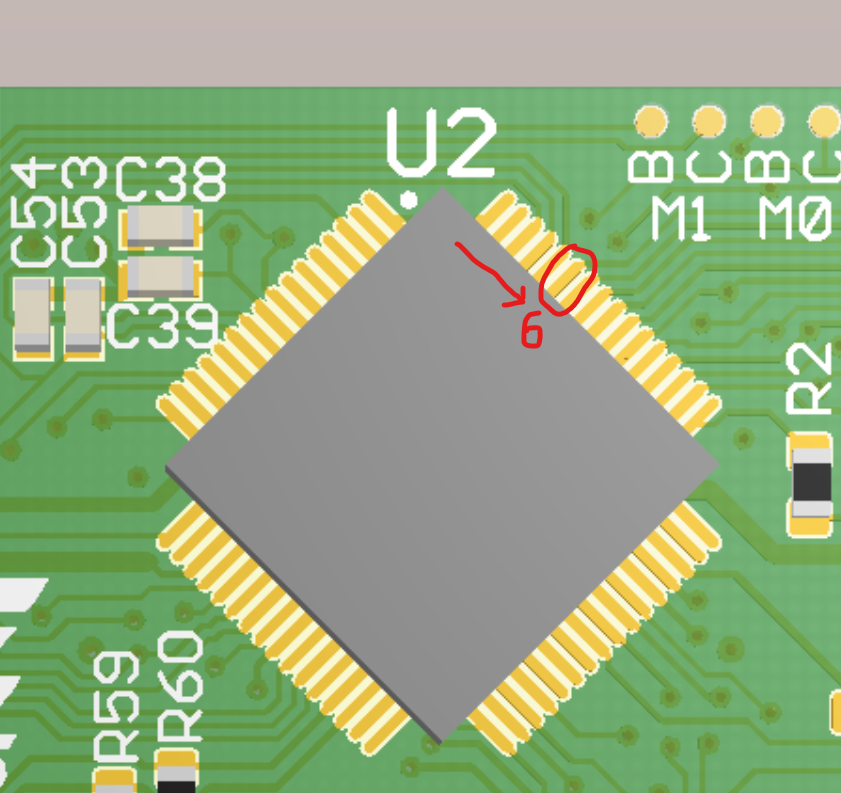
Am I missing anything? Where would be a good place to test the voltage with a scope (via, testpoint, pin), between J4 and the micro?