I’ve been reviewing the various posts on heat dissipation under loads such as @Richard_Parsons investigation and I’m curious if there is a good rule of thumb to calculate the heat dissipation per MOSFET in watts given various current levels?
I’m looking for ways to model the effects of various heat sink designs for the ODrive but I’m not clear on how to calculate the heat value for various loads.
A mosfet dissipated heat according to I^2 * R , where I is the current through the FET and R is the “Rds(on)”. Data sheet value. Check the graphs at the bottom to verify R at the temperature you want to run, since it changes. Also the FETs are in parallel groups of four two on the board. I don’t have the part number handy but a quick search on Here or asking on discord should pull it up
There’s also the transient switching energy. Rds doesn’t go from Rds(on) to Rds(off) and back again instantaneously - there is a slope for a few nanoseconds… There’s also the resistance of the PCB traces themselves. But for heatsinking purposes (assuming you don’t increase the switching frequency) the Rds(on) should be all that matters.
The part is NTMFS5C628NLT which has Rds(on) of 2.4 milliOhm, and they are in groups of 2, so I would assume 1.5 mOhm per phase for heatsinking purposes. (slightly higher than reality to account for switching loss)
A given current will be flowing through (in the worst case) two groups of mosfets in series, so assume 3 mOhm total.
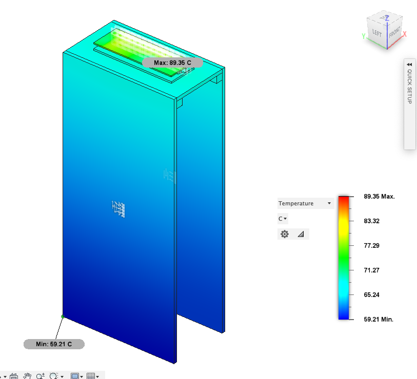
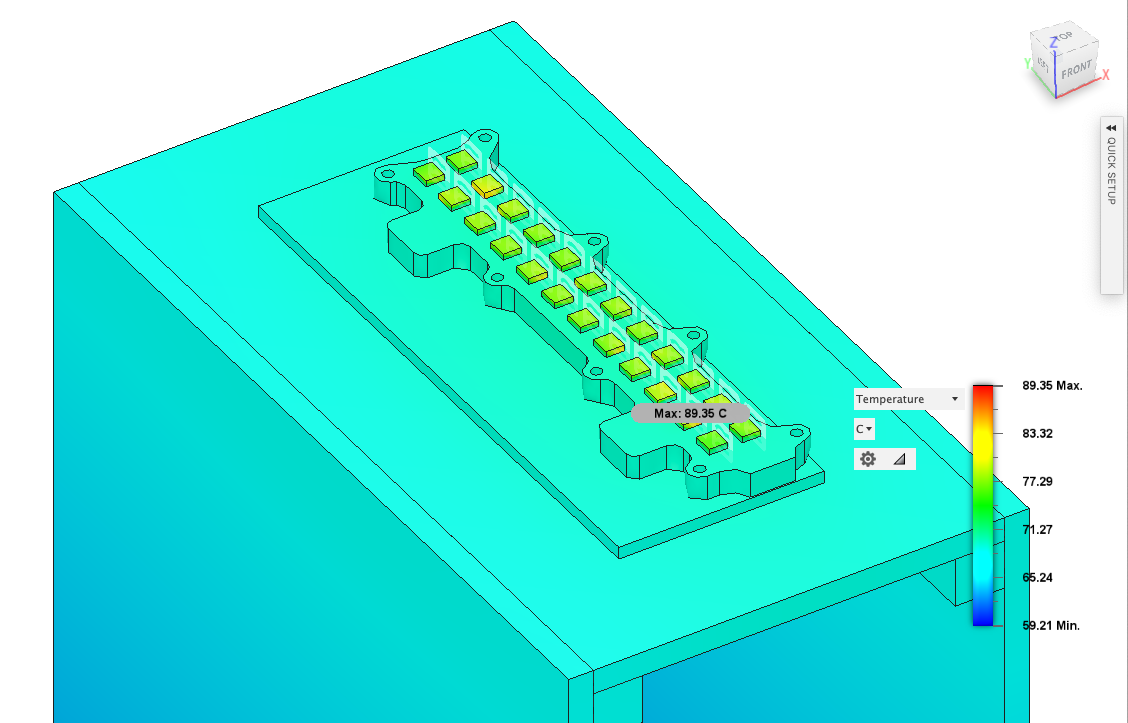
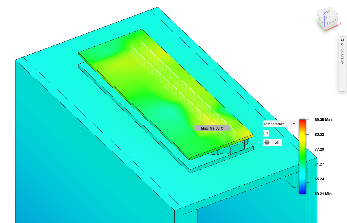
Update on this post. I’ve modeled a basic test case for a passive heatsink that is panel mounted similar to various industrial robotics controllers including the Roboteq KBL series. Our target is < 100C temps max.
Using @madcowswe formula above rated for 60A continuous we’re estimating a roughly 0.7W in power dissipation per mosfet for a total of 19.16W total. For those interested in modeling heatsinks I found a good basic tutorial on Fusion 360 Heatsink Modeling. The trick is figuring out a good convection load value. There’s not a ton out there for passive air convection coefficients so I’ve gone with a Natural Convection Coefficient Calculator as a starting point and derated our scenario by 50%. The models below are assuming a 2.5W/m^2K convection coefficient on the outside faces of our rovers side panels. Everything else here is just a thermal bridge. This is part of a larger enclosure project that I will likely start a project topic on as the next step here is testing.
Wow, cool, Did you do this with the Fusion360 personal version? Is it necessary to add some heat-conducting silicone grease between the FET and the heat sink, when simulating, if so and how?