Help Resolving Motor Cogging Issues

I’m currently in the process of designing/building a laser cutter/engraver machine. The movement platform is a Core XY system driven by two brushless motors. I’ve been able to setup the ODrive and control both of the motors, but the cogging motion exhibited by both motors is unacceptable for my application.
At most rotational positions the motors do an excellent job of tracking the setpoint. However at certain locations the motors will begin to “float” around the setpoint never actually settling on it. The below graph created with liveplotter shows an example of this. The Yellow line is the setpoint and the two additional lines represent what I consider an acceptable deviation for my application (a range of +/- 0.05 linear mm)


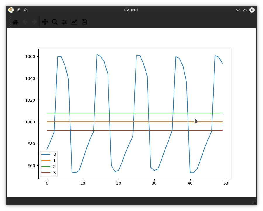
To reiterate, at most rotational positions the motor does track the setpoint well. I have tuned the motor so that with the exceptions of these cogging points the motors do track the setpoints well with minimal overshoot and no oscillations.
My setup is composed of two identical Turningy SK3 3536-1400 motors. They each have 12 stator coils and 14 permanent magnets. They are each attached to a CUI AMT-102 encoder. The issue ocours whether the motors are attached the the Core XY belt system or are disconnected from any load.
Things I’ve tried so far to resolve the issue:

  • I have tried re-tunning the gains on the control loop; both by repeating the calibration procedure from the ODrive docs and by fiddling with the gains manually.
  • I have tried using the partially complete anti-cogging support by running [axis].controller.start_anticogging_calibration() and waiting for the process to complete. The process seems to have difficulty completing because it has difficultly moving the rotor to the cogging point with similar results to the illustration above. I was able to complete the calibration procedure by adjusting the gains but interestingly this only seemed to make the issue much worse.

At the moment I am considering the following options for resolving the Issue

  • I could purchase new motors with less dramatic cogging issues. I’m not quite sure how to about this. If anyone could provide insight into how to purchase motors with less dramatic cogging I would be appreciative.
  • Could create a gearbox that would reduce the effect of this noise on the output of the system. I really don’t want to do this because of the engineering effort involved and the reduction of the speed of the motion platform (which was one of the primary motivators for using brushless motors linked to an ODrive).
  • Revise the entire design to use stepper motors instead

If anyone has any insight into how I could resolve the issue with the ODrive please post below. I would also like to know if anyone can think of any additional troubleshooting steps I could undertake to provide additional data. Finally I would also be grateful of anyone could recommend any brushless motors that do not exhibit such dramatic cogging characteristics. Thank you so much for taking the time to read through my post.

I suggest you to check:

  1. the linear motion setup. Try to cover working surface with a similar tool path.
    Maybe you get some pattern.
    If there is a problem with friction, you should get oscillation zone perpendicular to said axis.
  2. If you have long belts, it could be related with resonance frequency. I mean the belt works like guitar cord, same length, different sound. You can try to move roller to short the belt and repeat G-code at the same location.

Any way, if you need constant accuracy, thing first to change the belt for screw, or something more rigid.

And if you could make some photos…

I hope, it will help you

What cpr is your system set to? To better understand the scale of this vibration.

Having said that, the first thing is to get very familiar with the PID gains. A properly configured PID controller is usually operating near the edge of instability, and when it goes over that edge this is the type of behaviour you get.

Also you can try a motor with more poles. If you can still increase your voltage, or find a slightly lower top speed acceptable. That way you get more accuracy without adding a gearbox.

Thanks to both of you for your replies so far. @Bart_Slodzinski, I don’t think that the linear motion system is the root cause of the issue I am encountering, because the phenomenon is present even when the motor/encoder combination is completely disconnected from any load.
Here is link to a video that I took earlier that provides a good overview of the machine if you wish to take a look. Don’t worry, the flexing of the walls was resolved once I put the roof back on.
@Riewert the CPR is set to 8192 counts/rev. This is the max supported by the AMT CUI-102 encoders I am using.
As I said earlier I did spend a lot of time adjusting the various PID gains. I did manage to stop the oscillations I am having my ramping up pos_gain and vel_gain, but this caused the motors to massively overshoot while making large moves and also made the motors run really hot all the time so I’m not sure that it really works as a solution. Increasing and decreasing pos_gain independently only seems to vary the frequency of the oscillations shown in the graph above.
Purchasing a motor with a higher number of poles sounds like a potential solution. Is there a particular model of motor that you are familiar with and do you know of any other characteristics that I should look for to find a motor with low cogging?

So your vibration is approximately 100/8192 of a revolution, and you have coils every 1/12 and magnets every 1/14. I wouldn’t expect there to be enough control authority at that resolution, but I don’t have much experience with high res encoders. It sounds to me like more poles would definitely help. And maybe change the gains, so you at least get rid of the vibration. Have you been using the trapezoidal trajectory planner? That should help you limit overshoot for large moves, while keeping high gains.

Look for outrunners with lots of magnets, the flat ones. This one is wicked: https://hobbyking.com/en_us/9235-100kv-turnigy-multistar-brushless-multi-rotor-motor.html

Make sure you are also adjusting the vel_integrator_gain. In general you need to adjust all three. In my experience it is usually possible to balance on a cog of the SK3 motors with the 8k CPR resolution. But yeah it may take a lot of fiddling with the gains.
I wouldn’t suggest the current implementation of the anticogging, it has many issues right now and may not help as you noticed.
What will always help is a higher resolution encoder. Not sure if that is feasable for you, but you can nevertheless take a look here.

1 Like

Nice. I’ve pictured it a little bit different.
I see 2 motors in the corners. The belt goes on 2 levels, one for X, one for Y. So, one is just passing the X carriage???
If I get it right. It means you use one motor for each axis.

Is it possible you make another movie with the problem in progress??

I have never seen that solution in real, so it is quite interesting for me.
Now I see your point, it can travel very fast, and surprisingly smooth.

So, I agree about the number of poles, but I disagree about purchasing the motor.
I am pretty sure you can solve the problem without costs. I mean by that “understand” the problem.
If you expect accuracy and long service time, it is good to know and learn weak points. Because when you will be building big, heavy gantry machine in the future, you will know why it is done this, not that way.

First. You have very light (fragile) frame, and you have to avoid introducing “excessive forces”. So, the correct “number” of poles you can get with reduction box.

As you mentioned, you had done the PID regulation on many ways, but always with 50/50 outcome.

It seams you supply not enough torque or you demand to much from position. The last one you can adjust by lowering encoder resolution what is not an option for you (as you said), but it is the fastest way to test the idea. The objective is to get smooth and consistent result. Than you can back the encoder resolution, and by magnifying the torque, you should gain accuracy.

In this context, I disagree with Riewert :

In machining it is a must to have sufficient margin for condition changing, due to different stock dimensions, toolpath, ect.

`The gearbox/reduction box you can emulate by moving belt fixed points and replacing them with with idler rollers, what will double the step counts.

I am very curious about the result. So I would like to see feedback with your progress.
I am not implying you are wrong or I am right. I am just telling my experience, unfortunately not based on belts and pulleys.

Thanks you everyone for all of the advice given so far. I’ve spent several hours trying to fine tune gains and I have come the conclusion that I simply cannot get enough control authority from my current hardware setup to achieve my desired accuracy.
What really made clear that I wasn’t going to be able to fine tune the parameters enough is when I used Liveplotter to graph odrv0.axis0.controller.vel_setpoint and odrv0.axis0.encoder.vel_estimate and focused on trying to dial on the velocity control parameters.


This graph created while performing a constant velocity move at 400 cnts/s shows the considerable level of noise that remained in the system even after I tried to dial in ideal gain values. Worse yet was the fact that gain parameters that worked well at lower speed moves caused oscillations at higher speed moves, further confounding my tuning efforts.
Interestingly, the velocity readings on the graph appear to be in discrete steps suggesting that @madcowswe might be correct about using a higher-res encoder.
At this point I’m not sure what I will do next about resolving this issue. Thank you @Riewert for the link to the high pole-count motor. Unfortunately I think the price for the linked motor is too high to justify since the high power output of the motor does very little for my application. I may continue my search for some more affordable high pole-count motors, but at this point I’m looking into refactoring my design to use some nice stepper motors paired with the encoders that I have already purchased.
@Bart_Slodzinski The motion platform layout I am using is called a CoreXY system. Two of the primary advantages of this layout is that both of the motors can remain stationary and that it can be entirely implemented with a belt/pulley system. One of the major downsides is that the kinematics are quite unusual, when one motor moves and the other remains stationary, the head actually moves diagonally. If you are interested in learning more this is an excellent resource.
I’m blown away by the ammount of interest all of you have shown in my project. Thanks again to everyone who gave feedback and advice.

The control loop on the Odrive runs at 10kHz, you are sampling the velocity measured by the control loop through python at approximately 50 hz (?), so the noise is approximately 200x (?) less than you are graphing.

Also, take a look at the other multistar motors from hobbyking, they are pretty good. I linked the most expensive one, cause it’s the one I would really like to try out, haha.

Generally speaking it should always be possible to achieve at least, single-pole-width accuracy of moves. If you’re not using hall-effect-sensors then I would expect higher accuracy.

If the system is functional but oscillates at high speeds there are a lot of possible thing limiting your performance. Take a look at; the maximum amperage of your power supply, the max speed permitted by the trapezoid trajectory planner, the number of encoderticks produced at that speed with respect to the maximum number of ticks the encoder can generate electrically (e-rpm), etc etc.

Hi !
I just received my brand new ODrive 3.6 and have the same issue with this motor : https://hobbyking.com/en_us/turnigy-ld3730a-1000-brushless-motor-1000kv.html

Here a small video (40 sec) of the issue, with liveplotter. (set_point = 1800, 2000 cpr)

This is only happening in some positions for example in position “1700” it is completely fine, For my purpose (a sort of camera gimbal) this is not good…

I believe this inaccuracy is caused by the cogging torque of the motor

For now I didn’t tried to change gain values (parlty because IDK how :sweat_smile:, I’ll search)
Changing the max current changed nothing.

Any idea to solve this ? A different motor ? Adding a resistance to the displacement of the motor ? As the cogging torque is low, if the controller is working against a higher “braking” torque maybe that could help smooth out the position ?

(BTW : I’m new to this community, It is amazing. I’ve been trying for two month to do something with a modified VESC and no contact with the creator of that board, that was completed in 1 hour with an ODrive and so much information, imagine how happy I was)

Welcome to the fold @Trol. I do agree that the issue that your video demonstrates is similar to the issue that I’m having, though in my case it is less extreme. You will certainly get better results by going through the tuning process detailed here under the heading tuning parameters (Ctrl + F is your friend).
@Riewert I can confirm that I am easily achieving single-pole-width accuracy on all of my moves. Problem is that I’m targeting a precision of +/- 8 encoder counts or approximately 1/512th of a revolution. This may just be an unrealistic target with the hardware I have at the moment, but it’s what I feel that my machine requires.
Earlier today I tried experimenting by running the motor (with no load) at a constant velocity and discovered that there’s a threshold of about 5000 cnts/s (36 RPM) under which the motor will not move at all unless vel_integrator_gain is set to some non-zero value. If vel_integrator_gain is set the the motor sis stationary and then “jolts” very quickly once in while in the right direction. Obviously unacceptable in a machine that needs smooth motion, I’m gonna try attaching a flywheel to the motor shaft and see if that has any effect at least on the velocity control problem.

I’m affraid I don’t have any experience running Odrives at low speed velocity control, I only run position control. 36 rpm seems really slow to me though, on my Odrive system I wouldnt expect smooth tracking with my current gains.

Try taking your problem to the discord channel, maybe PM wetmelon, he should be able to tell you whether cogging is the issue or if something else is going on.

@Trol tune your gains! It will give you a lot insight into how stable your controller is!

Sorry to pollute the topic but I don’t know where to find the value “bandwidth” to tune the vel_integrator_gain in the guide.
I can’t find any information on this, should I create a topic for other users in my case ? Is it the “current_control_bandwidth” ?

@madcowswe is wright about resolution in general.
But what i mean in this case higher resolution feedback is like measuring rubber band with micrometer. “It is unlikely to cut it with this accuracy” read :“it is hard for driver to stop at exact position due to constant position feedback changing”.
So, if we spread the pulse angle (fe. count 5 encoder pulse for one, we “lower” the resolution, so to speak).

I send you pdf. It covers most of your problems. I hope at least.
Here is an example…

Blockquote
In order to sufficiently exert the servo motor capacity, it is important to efficiently pull the servo motor power and to use the servo system that includes the machine by increasing its stability and response. For this, the major element is the reduction ratio, which is introduced between the servo motor and the machine. The conditions for selecting the reduction ratio correctly are explained below.
(1) To use the maximum motor output (power), select so that the motor is operated at the rated speed when the machine is at its fastest. 1) The servo motor gives the maximum output (rated output) at the rated speed. 2) The load torque at motor shaft and load moment of inertia at motor shaft of the machine decreases when the reduction ratio increases. In other words, when the reduction ratio is selected so as to operate at the rated
speed, the observed load from the motor will become lighter.

and you can get it from here:
[AC Servo School Text. AC Servo Practice Course. (MELSERVO-J4)]
(https://dl.mitsubishielectric.com/dl/fa/document/manual/servo/sh030146/sh030146a.pdf)

Did you remember to put your gains lower again once it was done? You may have traded a cogging torque issue for a “hunting” problem. I tend to disagree with Oskar that the Anticogging isn’t recommend in its current iteration. It has SOME problems (such as having to tune very aggressive gains during calibration to get it to calibrate) but it can make a big difference once done properly. We’ve been planning anticogging improvements for quite some time, hopefully we can get it done soon.

Today I built a flywheel out of a stack of washers and the preliminary results are very promising. The system now easily tracks a postion setpoint within the margin of error while not attached to the machine. I’m traveling this weekend, but when I get back I’ll be sure to post about my results when integrated into the machine.

I successfully resolved my issues of cogging by getting pos_gain to 300 (yes, that’s high, but perfect for me), vel_gain to 0.007 and integrator to 0

The vel_integrator_gain value was causing overshoot.

I also added some absorbent paper rubbing against the motor bell. It helps getting rid of vibration, stabilizing the position.

With all of this, I’m able to get a setpoint accuracy of ± 1 cpr ! With an AS5047P having 2000 cpr

No vibration at all. (sometimes without the paper, nothing once in place)

Very happy with that, hope you find a solution to your problem !

(also I still don’t know how to calculate a proper value for the vel_integrator_gain, maybe a better explanation in the guide would help !)

1 Like

Wow, it’s been a while but I wanted to report back that the addition of the flywheel seems to have greatly improved the handling of the motor. I just put together a stack of washers and attached them to the back of the motor with a 3d printed spacer and some of the mounting hardware that came with the motor. Thanks to everyone who assisted me in working through this issue.

1 Like

@robopilot99

I built a corexy system about the size of your own, maybe bigger. In my usecase precision is not very important (+/- 1mm is ok), torque/repeatability is more important. For a laser machine precision does matters.

I did observe similar cogguing issues myself, even without load just like you. Your video does not clearly show it, but it seems you may reduce the importance of such issue by simply using smaller pullies (how many teeth do they have?) => But then you trade speed for precison :confused:

I did try to tune the pid controller, it helped but did not eliminate the behavior entirely.
In the end, I decided to live with the imprecision caused by the cogguing but I would really like to eliminate it.

I am not very familiar with the concept of a flywheel. Is that it? (https://youtu.be/7K4W4hA6aV4)
We discussed a flywheel on the forum, something rather heavy (about 5-10kg), in order to add some dummy load to stress test the trapezoidal trajectory planner. But in the end, I observed unexpected/dangerous moves with this planner on my machine so I used my own planner instead (did not have time to investigate sorry).
I struggle to understand how such a concept (inertia on the main shaft) can possibly help with cogguing, in particular in the context of a fast corexy machine for laser engraving where the motors will quickly and frequently change both speed and direction during a laser job.

Can you please post a closer video of the motoring system in operation ?
Can you please post another screenshot of pour set_point around 1000 to compare with your original post?

Side note: it turns out that I made and operate a lasersaur! I use it very often, mostly to cut acrylics (rarely for engraving). It accepts svg files and does the gcode alone. I noticed that it certainly uses an algorithm to minimize the cutting path. Therefore, transitions between cutting segments (when the head needs to travel fast) are not that frequent. And for cutting the head does not need to go fast at all for cutting 3/5/8 mm acrylics. In other words, having a fast laser machine is useless to me.
=> Do you engrave a lot? Are your material to cut thin?

Your machine seem to use v-slot extrusions for openbuilds.com, am I mistaken?. Their concept with the plastic wheels seems very good for precision, speed, price and durability. much Better than the lasersaur design (I have the 2016 revision with metallic bearings rolling on aluminium. It’s not great). Are you happy with it? What are the pros/cons in your experience?

Hey @alexisdal. I’ve had to put this project on the back burner for a little while. When I start back up again I’ll take a video and send it to you. My understanding of the flywheel behavior is that before I added the flywheel the motor wanted to “stick” in certain positions. The flywheel I’m using isn’t very big. Probably only about 100 grams. They don’t seem to have too great an impact on the motor’s ability to change direction quickly, but that will be something I look more into as I continue testing. Since I added the flywheel it now continues to move smoothly past these points. A screenshot of the pos_setpoint graph wouldn’t be very interesting as now the actual value just tracks the setpoint within a count or two. You are correct that I am using the openbuilds V-slot rails and carriages. I don’t have a ton of experience designing machine systems but they so far are performing quite satisfactorily. They move quite smoothly and seem to be very cost-efective. Not sure how they’ll hold up in the long run, but the plastic wheels are cheap enugh.