Hello. I got the AMT10X encoder and I was wondering when connecting the encoder to the Odrive the wiring is as simple as A to A, B to B, GND to GND, and so On. Thanks
Yes the wiring is that simple. Remember to set the correct cpr in the firmware!
1 Like
Thanks very much. The file MotorControl/low_level.c, line 37, is coded as follows:
#define ENCODER_CPR (2048 * 4) // Default resolution of CUI-AMT102 encoder.
is this the line that handles the CPR resolution?
What is the “meaning” of numbers “2048” and “4”?
Should all DIP switches should be on OFF position to follow the 2048 CPR on the encoder?
On PDF below, page 4, the manufacturer depicts the switch resolution settings
AMT102V encoder
I am new to all this; my motor is not spinning and I trying to narrow all possibilities to tackle the problem. Thanks for your help
Does the motor not turn at all or only stops after startup? Also, I think this might be the wrong spot to ask for support questions, maybe think about posting in a new topic and photos are always helpful 
I just moved this to a new thread
#define ENCODER_CPR (2048 * 4) // Default resolution of CUI-AMT102 encoder
The 2048 corresponds to the PPR setting of the encoder, which is indeed when all DIP switches are in the OFF setting, as you can see in the datasheet.
In the Firmware Readme it’s written:
ENCODER_CPR: Encoder Count Per Revolution (CPR). This is 4x the Pulse Per Revolution (PPR) value.
PPR means Pulses Per Revolution, and CPR means Counts Per Revolution. CPR is always 4x the PPR value.
Here is why:
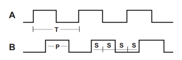
In a quadrature encoder, the frequency of states S are 4x higher than the frequency of pulses P.
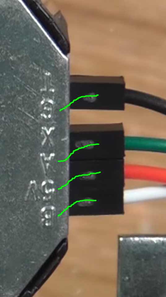
Hello and thanks.As far as the encoder and the Odrive connections, I have what I mentioned above :“as A to A, B to B, GND to GND, and so On”.When researching, I found that the “T” connector on the encoder was used instead of the “G”. Does it make any difference which one to use when connecting it to the Odrive? What’s the right way?
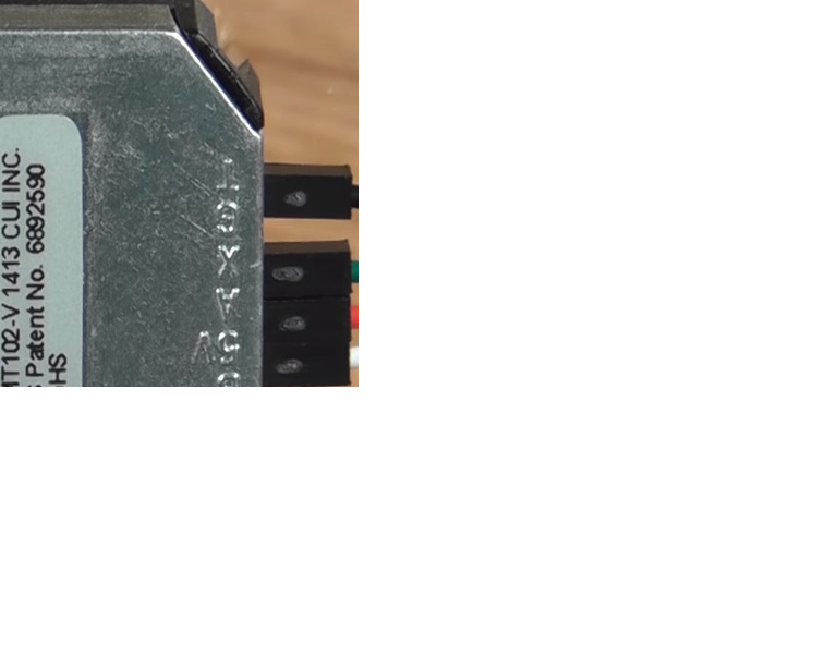
G is GND and should be connected. T should never be connected. Also in the video you show, they do not use the T connection, it’s just a deceiving camera angle since the pins are much further away from the camera than the face with the markings.