I may order this oscilloscope
https://ru.aliexpress.com/item/Fully-Assembled-Orignal-Tech-DS0150-15001K-DSO-SHELL-DSO150-DIY-Digital-Oscilloscope-Kit-With-Housing-case/32826369650.html
will it suit for measure?
What method do you use to measure the resistance? The resistance between two phases on N5065 should be 0.066ohm. A normal multi-meter is not accurate enough to measure so small resistance. The best way to measure is to use ODrive (if that is working  ), or to use a bench power supply like this:
I don’t think a higher calibration_current would help, it looks like we are drawing too much power from the supply, which is not good.
Yes that oscilloscope will be able to detect the dip I think.
Ok
Today i will assemble scheme based on LM317, measure resistance and send exact value
Cool! Make sure to test all 3 phase pairs.
I have done measurements of resistance
For N5065 i got = 0.0898 Ohm
For Magic Pie = 0,325 Ohm between all wires (green-yellow, green-blue, yellow-blue)
It is interesting that n5065 slightly move during measurement (the current was ~1A )
but Magic pie even did not think to do this
Okay that is very strange. I can expect maybe you can get error 3 ERROR_PHASE_RESISTANCE_OUT_OF_RANGE, but not dc bus brownout, it doesn’t make sense  .
.
Taking master branch as the base, what exact settings did you change?
main.h
#define HW_VERSION_HIGH_VOLTAGE true
commands.h
#define USB_PROTOCOL_NATIVE
#define UART_PROTOCOL_LEGACY
low_level.c
#define ENCODER_CPR (600 * 4)
#define POLE_PAIRS 28
.motor_type = MOTOR_TYPE_HIGH_CURRENT,
Today I turn on the power source, connect USB cable and run explore_odrive.py without motor
and then i get code 3
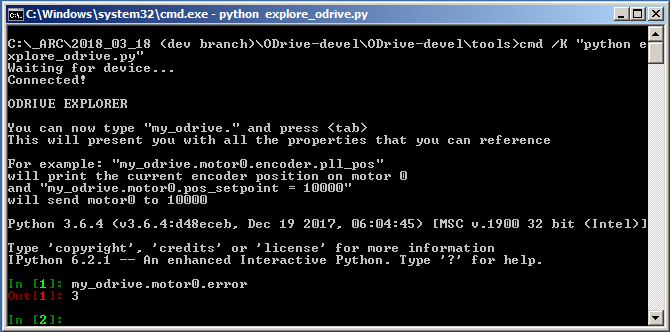
After that i connect motor and do the same then i get code 3 too !!!
I dont know why it happened, i didn’t reflash Odrive
Anyway this is really ERROR_PHASE_RESISTANCE_OUT_OF_RANGE
It seems I’m almost close 
What i have to do know?
I saw your recommendations in other topic for ERROR_PHASE_RESISTANCE but i afraid to fry the second Odrive , so i will wait for answer
I have one more question - when i turn on the power source and connect ODrive to USB do i need to disconnect STLink totally?
Because usually i only disconnect usb cable and leave it connected like this
And what will happen if i turn on Power Source with connected ODrive to USB and STLink to USB ?
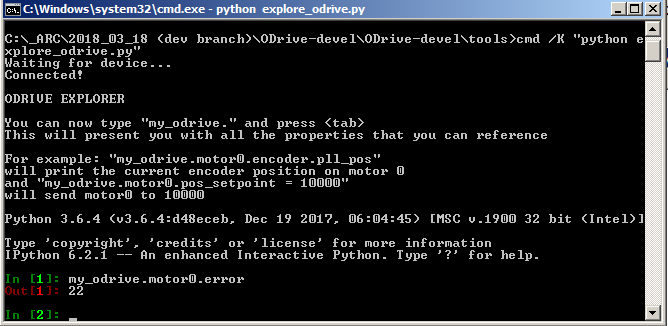
Great! That means everything is working. I don’t know what has changed, but you should be good now: Error 3 is expected when the resistance is that high for the Magic Pie.
You can set .resistance_calib_max_voltage = 4.0f.
I think it should be ok to disconnect the ST link in the way you show.
I set .resistance_calib_max_voltage = 4.0f
and now with #define ENCODER_CPR (600 * 4) motor does initial move
but i get the error
I accurately measured the ratio between the motor and encoder => 1:9.75
When i set ENCODER_CPR (5850 * 4) the ODrive disappear from Windows and Zadig find ‘Unknown USB Device’
With smaller ENCODER_CPR value everything is ok and Odrive in the Windows
It seems that I was not able to install the driver in Zadig before because I set ENCODER_CPR (6000 * 4) at that time
Ok we are very close. The problem is that malloc is actually broken, it won’t say no if you ask for too much memory. We fixed this in a branch and will be released soon.
But in the meantime you can comment out the malloc line in axis.cpp:
legacy_motor_ref_->anticogging.cogging_map = (float*)malloc(encoder_cpr * sizeof(float));
Yes, it works
Thank you very much !!!
I commented all this block (just in case)
//legacy_motor_ref_->anticogging.cogging_map = (float*)malloc(encoder_cpr * sizeof(float));
//if (legacy_motor_ref_->anticogging.cogging_map != NULL) {
// for (int i = 0; i < encoder_cpr; i++) {
// legacy_motor_ref_->anticogging.cogging_map[i] = 0.0f;
// }
// }
my_odrive.motor0.error returns 0
There is video i made (i ran demo.py)
I have some quesitons about intial move and position speed I will write it today later after tests
Awesome!! 
Okay.
Question about initial move:
In your video
you show how to make a robotic arm. My arm will look like just bigger. Therefore, taking into account the design features, I need to find out a few things.
As I understand it when turning on Odrive all 3 motors of arm will do the initial movement to determine how the phases of the motors are connected.
In initial move motor rotate from one side to other side.
What if motor can’t rotate enough because there are some bounds due to arm design?
There may be damage to the robotic arm itself and initial move will not be able to determine the phases
I made the demonstarting picture to better explain
How to limit this initial movement?
If the phase connection is not changed then why have to do the initial movement every time?
Another question
In Odrive there is command my_odrive.motor0.pos_setpoint = 10000
Lets imagine that i want to move arm to 0 degree
0 degree equal position 0?
What if arm starts from different positions then after turning on power and initial move we will get random unknown start angle?
I think that an angle sensor is needed here to put a correspondence between the real angle and the Odrive position count, which it receives from the encoder.
If so, then this may be approached by non-contact variable resistor.
I’m sure that you have already provided for this, but I could not find a solution on the forum so I apologize for this possibly obvious questions
I hope in the future it will be possible to store the motor settings in the outside Odrive and just load them each time when you need to bypass initial move
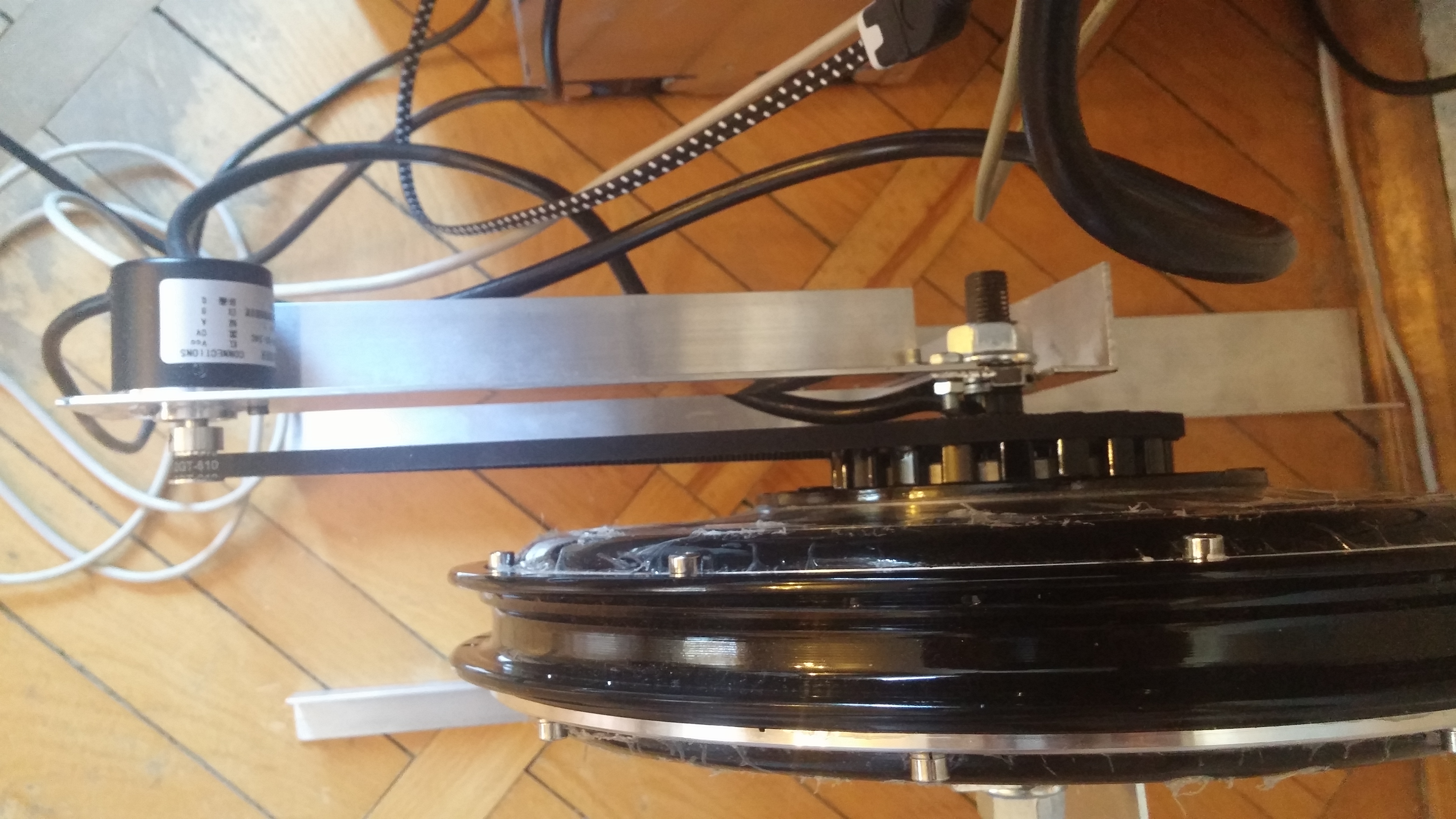
Now, while there is no suitable solution, I installed additional variable resistor and moved the encoder so that it is directly connected to the motor
I plan to turn on the Odrive power by these steps:
- Arduino is turned on first, the current position angles are checked with the help of the variable resistors
- If the future initial movement causes damage, a message is showed and everything stops. If everything is normal, then power is supplied to the Odrive using a power relay
- The values of the variable resistors after the initial movement are used for determine the zero position
I also prepared for the weight holding tests with high current and increased the cooling of Odrive
Also, I chose the optimal quadratic functions for acceleration and stopping to avoid shock loads when moving to the required position (by command odrive.SetPosition)

P.S. My first ODrive works too, It isn’t burned
I have a few questions:
-
Which parameter in low_level.c is responsible for that with which current and speed the motor trying to return to specified position ?
With ENCODER_CPR (600 * 4) the motor not so confidently holds a position -
After i power on ODrive and send Arduino command odrive.getBusVoltage() then i start get values immediately. Even if Odrive still performs the Initial move.
How it can be defined that the inital move is already completed and i can start sending the positioning commands? -
Could you give me a link with a description or expression of how to calculate odrive.SetPosition by
odrive.GetParameter (motor, odrive.PARAM_FLOAT_ENCODER_PLL_POS) ?
Because these two values are not equal
Well, i answer by yourself
In arduino library there are params which let you know the state of Odrive by runnig a command
odrive.GetParameter(< motorNumber >, < param >)
odrive.GetParameter (0, odrive.PARAM_INT_ERROR) allows to get an error from the motor after calibration
I run the command odrive.SetPosition(0, 10000);
After process finished I run this commands for a few seconds
odrive.GetParameter(0, odrive.PARAM_FLOAT_ENCODER_PLL_POS)
odrive.GetParameter(0, odrive.PARAM_FLOAT_POS_SETPOINT)
Why are such unstable values returned?
PARAM_FLOAT_ENCODER_PLL_POS 9.0000
PARAM_FLOAT_ENCODER_PLL_POS 9976.8818
PARAM_FLOAT_ENCODER_PLL_POS 9.0000
PARAM_FLOAT_ENCODER_PLL_POS 18007.4003
PARAM_FLOAT_ENCODER_PLL_POS 9.0000
PARAM_FLOAT_ENCODER_PLL_POS 9.0000
PARAM_FLOAT_ENCODER_PLL_POS 9.0000
PARAM_FLOAT_ENCODER_PLL_POS 18810.0000
PARAM_FLOAT_ENCODER_PLL_POS 9.0000
PARAM_FLOAT_ENCODER_PLL_POS 18006.0996
PARAM_FLOAT_POS_SETPOINT 18000.0000
PARAM_FLOAT_POS_SETPOINT 18000.0000
PARAM_FLOAT_POS_SETPOINT 18000.0000
PARAM_FLOAT_POS_SETPOINT 18000.0078
PARAM_FLOAT_POS_SETPOINT 18800.0000
PARAM_FLOAT_POS_SETPOINT 18000.0000
PARAM_FLOAT_POS_SETPOINT 10000.0000 !!!
PARAM_FLOAT_POS_SETPOINT 18000.0000
PARAM_FLOAT_POS_SETPOINT 18000.0000
PARAM_FLOAT_POS_SETPOINT 10000.0000
Is it normal that
PARAM_BOOL_DO_CALIBRATION
PARAM_BOOL_CALIBRATION_OK
return 0 always?
Even if the calibration is completed(finished) successfully
There is all params for Magic Pie after calibration:
PARAM_FLOAT_ENCODER_PLL_POS 1.0000
PARAM_FLOAT_POS_SETPOINT 0.0000
PARAM_FLOAT_POS_GAIN 2.0000
PARAM_FLOAT_VEL_SETPOINT 0.0000
PARAM_FLOAT_VEL_GAIN 0.0000
PARAM_FLOAT_VEL_INTEGRATOR_GAIN 0.0000
PARAM_FLOAT_VEL_INTEGRATOR_CURRENT -8.0000
PARAM_FLOAT_VEL_LIMIT 28000.0000
PARAM_FLOAT_CURRENT_SETPOINT 0.0000
PARAM_FLOAT_CALIBRATION_CURRENT 18.0000
PARAM_FLOAT_PHASE_INDUCTANCE 0.0000
PARAM_FLOAT_PHASE_RESISTANCE 0.0000
PARAM_FLOAT_CURRENT_MEAS_PHB -8.0000
PARAM_FLOAT_CURRENT_MEAS_PHC 0.0000
PARAM_FLOAT_DC_CALIB_PHB -8.0000
PARAM_FLOAT_DC_CALIB_PHC 0.0000
PARAM_FLOAT_SHUNT_CONDUCTANCE 1.0000
PARAM_FLOAT_PHASE_CURRENT_REV_GAIN 0.0000
PARAM_FLOAT_CURRENT_CONTROL_CURRENT_LIM 28.0000
PARAM_FLOAT_CURRENT_CONTROL_P_GAIN 7.0000
PARAM_FLOAT_CURRENT_CONTROL_I_GAIN 1.0000
PARAM_FLOAT_CURRENT_CONTROL_V_CURRENT_CONTROL_INTEGRAL_D -8.0000
PARAM_FLOAT_CURRENT_CONTROL_V_CURRENT_CONTROL_INTEGRAL_Q -8.0000
PARAM_FLOAT_CURRENT_CONTROL_IBUS 0.0000
PARAM_FLOAT_ENCODER_PHASE -8.0000
PARAM_FLOAT_ENCODER_PLL_POS 0.0000
PARAM_FLOAT_ENCODER_PLL_VEL 0.0000
PARAM_FLOAT_ENCODER_PLL_KP 2800.0000
PARAM_FLOAT_ENCODER_PLL_KI 1800000.0000
PARAM_INT_CONTROL_MODE 2
PARAM_INT_ENCODER_ENCODER_OFFSET 3
PARAM_INT_ENCODER_ENCODER_STATE 0
PARAM_INT_ERROR 0
PARAM_BOOL_THREAD_READY 1
PARAM_BOOL_ENABLE_CONTROL 1
PARAM_BOOL_DO_CALIBRATION 0
PARAM_BOOL_CALIBRATION_OK 0