Help with setting up ODrive to work with Magic Pie motor

Hi, sorry I took a while to answer.

There are 3 ways to keep the encoder calibrated:

  1. Run the encoder calibration on every startup. This is default if you don’t configure the other options.
  2. Use an encoder with Index output, sometimes called “phase Z”. This means you don’t run the calibration, but you still need to spin the motor to find the index. We have support for this.
  3. Use an absolute encoder. This means you don’t need to move at the start.

For nr 2 and 3 you can only use it if either

  1. your transmission ratio is a factor of your pole pairs. So because you have 28 pole pairs, you can only use this option if your transmission ratio is exactly: 1:1, 2:1, 4:1, or 7:1.
  2. OR you have a separate encoder on the wheel directly also: so you have some other encoder/potentiometer on the wheel, and still the large ratio to the encoder (not exact factor of 28). You need to add some logic that uses the knowlege of which “turn” the encoder is in, derived from the wheel encoder/potentiometer.

Yes you are absolutely right, the position control reference position is just 0 at where the encoder was on startup. You can use a home switch, or indeed a potentiometer like you suggest:

yes. But you need to add some code for this, as we don’t have it available yet.


The future is today! This is due to be released soon, and you can already try it on devel.


:tada: :grin:


To increase the speed attempted to control to the setpoint with, increase pos_gain. To increase the current used to achieve the correct speed, increase vel_gain. You can play with both together, a general description is here.

I don’t think you can see this on the Legacy protocol, sorry. We don’t have much support for that protocol, and we recommend to use the Python USB protocol. We will in the next couple of weeks roll out a new ASCII protocol for use on UART, and there it should be much better. Until then sorry you may have to just wait a fixed ammount of time for now, or hack in your own variables in the exposed variable table.

They should be equal if the tracking is good. If they are not close, then you need higher gains to get the tracking to be better.


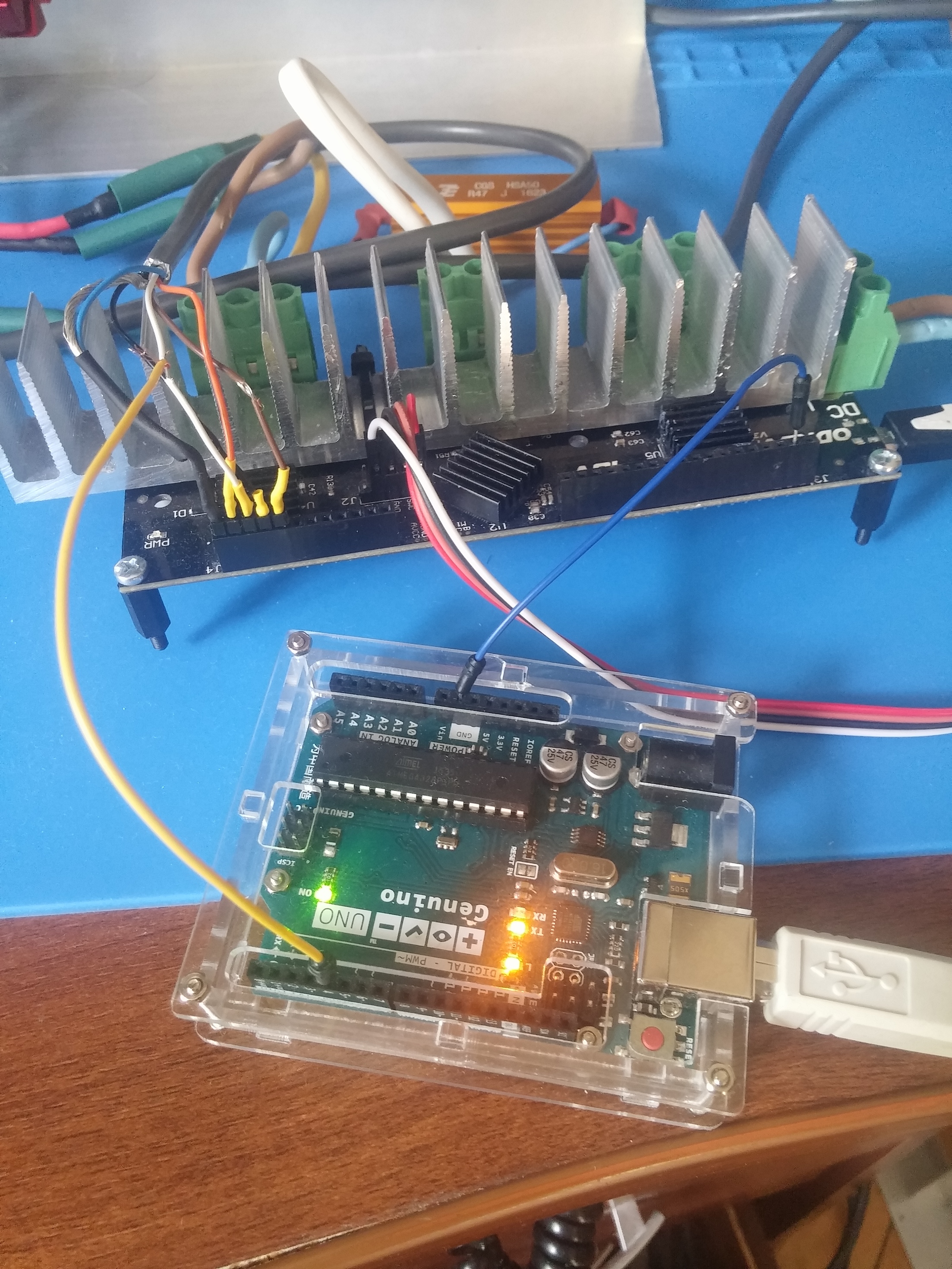
I assume you are using SoftwareSerial on the Arduino? SoftwareSerial is rally crap, and it’s better if you use a more powerful arduino like Teensy (recommended), or Arduino Mega.

No, the reason you see that is because it was left out of a half-done refactoring, so those values don’t work right now. This will be fixed with the new ASCII protocol.

Thank you very much for the detailed answer.
Sorry, i did not fully understand the part about absolute encoder.

I have non-contact potentiometer (aliexpress.com/item/DC-5V-Hall-Angle-Sensor-Non-contact-Industrial-0-360-Degree-Rotation-Angular-displacement-Sensor/32422949989.html)
and 12bit ADC ads1015 (aliexpress.com/item/1PCS-ADS1015-12-bit-precision-analog-to-digital-converter-ADC-development-board/32687298768.html)

May i connect potentiometer via ads1015 to Odrive instead encoder?

On the other hand if I had a zpulse encoder then I would need to:

  1. attach encoder and potentiometer to the motor with transmition ratio 1:1
  2. calibrate once
  3. set my_odrive.motorN.config.*
  4. set
    my_odrive.axisN.config.enable_control = Falsе
    my_odrive.axisN.config.do_calibration = Falsе
    .encoder.calibrated = true.
  5. save the settings - my_odrive.save_configuration()
  6. every time Adruino starts first and with help of potentiometer i get direction to find index pulse (вecause when power on the robotic arm can be in different positions).
  7. after that Odrive power on and before Odrive starts (?) find index pulse i have to set
    .encoder.idx_search_speed ()
    or
    my_odrive.motor.encoder.encoder_offset.
    my_odrive.motor.encoder.motor_dir

After that, Odrive will not do the calibration every time after power on
and will only do the motion to determine index pulse in the right direction and stop at this point as position 0.
Right?

If so, then probably a zpulse encoder+potentiometer is better solution
Could you recommend me some zpulse encoder with high resolution, please?
For example I found this and don’t know will it suit or not
resolution 5000ppr : aliexpress.com/item/-/32854557987.html
resolution 5000ppr : https://www.ebay.com/itm/NEW-ENCODER-A58D-TTL-5V-5000PPR-PRECIZIKA-METROLOGY-ID50526/173229355252 from https://www.rgbautomatyka.pl/en/enkodery-i-elementy-pomiarowe/enkodery.html#!/no_cache=true&service_type=&p=1
resolution 3600ppr : aliexpress.com/item/E6b2-cwz3e-50-100-200-360-500-600-1000-1024-1500-2000-P-R/32834407089.html
resolution 3600ppr : https://www.ebay.com/itm/1PC-Brand-New-In-Box-Omron-encoder-E6C3CWZ3EH-E6C3-CWZ3EH-3600P-R/322655114385

Now I’m looking forward to the new ASCII protocol and will try to work via it in Teensy

Thank you very much for your work!

In my task, the manipulator will have to take objects from the moving tape.
Therefore I have to move the manipulator’s grip to the tape, then move over it at a specified speed, grip object and put it in the basket.
And I already see that with Odrive I can solve it.

No sorry the ODrive doesn’t have any I2C ports available. If you can find an ADC with SPI interface, that will work ok I think.


Yes your proposed sequence should work, though I think it will give you a higher encoder resolution, so you can use a cheaper encoder, if you use transmission ratio 4:1 or 7:1 on the encoder. The potentiometer should still be 1:1.

Yes I think any of those encoders will work.

Here is

So i get absolute SPI encoder.

And here is

How can I connect them to Odrive instead of the incremental encoder and how should I do the calibration once?
In master and devel branches there is a description for Z index encoder only.

I really want to try to make so that i do not have to do calibrating and look for index all the time after turning on.

The main control loop only runs on the incremental interface right now.
If you get something like this one, you can use both absolute position over SPI for initalization, but then run the control on incremental afterwards: https://www.digikey.com/product-detail/en/ams/AS5047P-TS_EK_AB/AS5047P-TS_EK_AB-ND/5452344

We don’t have any code for absolute encoders yet: some people in the community have tried it, but nobody has made a pull request with it yet.

The encoder with Z index would still be a temporary palliative and it would be best to use an absolute encoder.
I decided that I will assemble my robotic arm completely using a simple incremental encoder and then it will be seen how best to proceed. Maybe and you will have some new improvements for Odrive by that time.

Hello
I have finished testing the new encoder 2500 ppr with Z index
aliexpress.com/item/GHS3806-pnp-signal-output-2500-PPR-optical-linear-encoder-reflective-optical-speed-encoders-with-cable/32810781565.html
it work’s good

I don’t quite understand this part you wrote “your transmission ratio is a factor of your pole pairs. So because you have 28 pole pairs, you can only use this option if your transmission ratio is exactly: 1:1, 2:1, 4:1, or 7:1”

I want to use gt2 belt and pulleys of different sizes to increase ppr so i need to know is that transmition ratio also for pulleys?
So if i want to have maximum ratio then i need (for example) pulley with 20 teeth and 7*20=140 theeth pulleys?

Yes, you understood it correctly. :slight_smile:

Today I made several tests to find out the possible load of the motor with different currents
(i did them with 2500 ppr Z index encoder and with default 600 cpr encoder)
With max current = 10A i got maximum load 1 kg on shoulder 1m
When i set max_current = 30 A i have some problems

looks so my odrive lacks power. I get some weird errors.
I get turning off the motor with an error 20 if current_limit more than 10.0f.
Turning off occurs when I trying to apply a force and rotate the motor from set position

It happend with Magic Pie and N5060

Probably somewhere there is a loss of current. How can this be verified?

-------- Magic Pie --------
Here is the video where the motor turns off after a while if i apply a force with error 20 (20A, 2500 ppr encoder .use_index=true) https://youtu.be/EwSUimDZ7oc

Here is the video where the motor turns off almost immediately with error 20 (10A, 2500 ppr encoder .use_index=false) https://youtu.be/PVnwPBquiEU

Here is the video where cur_lim =2.0f and everythig is ok, no errors, the motor doesn’t turns off https://youtu.be/WqJm22GtKGA (2A,2500 ppr, use_index=true)
I can rotate motor as i wish, but if i send SetParameter(…,20f) then it will turn off if i apply a force

Here is the video i made with oscilloscope connected to the bus voltage https://youtu.be/zjvwrl-6fCU
Bus voltage stays about 48 V (20A, default encoder 600 cpr)

Pulleys ratio always 1:9.75

-------- n5060 --------
This also happens with n5060 when cur_lim = 30f, here is the video https://youtu.be/oo6D2SFX8CY (n5060, default encoder 600 cpr, 30A)

In generally, what does mean error 20?

---- My settings in low_level.c:----
.pole_pairs = 28
.resistance_calib_max_voltage = 4.0f
.current_lim = 02.0f - 30.0f

.encoder_cpr = 5850 * 4 for default 600 cpr encoder
.encoder_cpr = 24375 * 4 for 2500 ppr encoder
.use_index=false or true

Сould you tell please how can i check Z index encoder by osciloscope?
Sometimes i get this https://youtu.be/QVcy4Hxtdj8 strange behavour when
.use_index =true, .manually_calibrated = true,
Looks like encoder cant find z pulse, but usually all is normal.

I still doing varios tests… If something clears up, I’ll write more accurately

I am trying to make compact industrial manipulator
I already planned pneamatic and mechanic parts and get ready to assemble their together.
But i can’t start because this weird errors.
here is prototype model


Thanks for the detailed presentation on the issue with error 20.

You can check what the error codes mean by reading the documentation. Error 20 is DRV_FAULT. You are experiencing an hardware bug that is present in ODrive v3.4, and is further explained here. In that post I suggest a mod that you can try. If that mod doesn’t work I can send you an ODrive v3.5 as a replacement: the DRV fault has been tested to be fixed in v3.5.

Cheers.

unfortunately I did not manage to correct the error.
I re-soldered capacitors but now i have this behavior https://youtu.be/kU1QT81mEJo
I tried not to overheat the board and I did it like this

I understand that product development is iterative and I am ready to support the project. Therefore, I am ready to order ODrive 3.5 (i have 3 motors, so i need 2 boards)

One more question
Сould you tell please how can i check Z index encoder (by osciloscope or something else)?
Sometimes i get this https://youtu.be/QVcy4Hxtdj8 strange behavour when
.use_index =true, .manually_calibrated = true,
Looks like encoder cant find z pulse, but usually all is normal.

That is actually because the calibration current is too low and/or the friction is too high and the motor can’t turn.

This happens if the ODrive sees the index pulse in the wrong place, or you write .manually_calibrated = true but didn’t write the correct value in .encoder_offset. You must:

  1. run use_index = true and manually_calibrated false
  2. run calibration
  3. read out .encoder_offset and write into firmware
  4. set also manually_calibrated to true

If you did all this correctly, then it could be electrical. Yes you can check with oscilloscope.

Yes, it was too low calibration current 2.0f, in any case before it was enough to calibrate
After I set .calibration_current=10.0f and .current_lim=30.0f i got the same turning off n5065

I need to clarify one thing
You wrote

Does this mean that I should warm the board so that the solder penetrates through the hole to the back side? Or just solder like I did?

I have one more strange behavior with Z index encoder (i just want to apologize for my English, but I need to solve these problems)
I found this behavior when I tried to reduce the initial motion of the motor to find the index and set the motor already in the position where the index is
I got the same behavior with a big motor (Magic Pie) too.
I have to say that this behavior does not occur in every initial position and I had to look for it.
Also, it does not happen every time when i turn on the power.
I used a non-fixed ODrive 3.4 with no resoldered capasitors c35,c50 with a current =10A.

The behavior shown in the video below, before I did the following:

  1. i rotated the motor so that the mark (cut off part) on the encoder was on top

  2. i set use_index=true and manually_claibrated =false in firmware and flashed the board

  3. after that i turn on power and then motor slighly rotate from position by itself,
    it rotates so that the mark slightly shifted

  4. After initial move finished i run explore_odrive.py get the offset = -6105 and set it and manually_claibrated =true in firmware

  5. Now when i power on with the mark on top then all is normal
    when i power on with shifted mark i get this behavior


On this video

  1. the mark on the top
  2. I rotate the motor to show the position with shifted mark (to that position motor rotates by itself)
  3. i set mark on the top again and turn on the power - there is no error and the motor rotates to the position when the mark is shifted
  4. I turn off the power and turn it on again ( the motor is in exactly the position with shifted mark and this position to which it rotates by itself)
  5. so strange behavior of the motor is obtained.

Settings:
Motor - N5065
Encoder 2500ppr NPN (aliexpress.com/item/GHS3806-pnp-signal-output-2500-PPR-optical-linear-encoder-reflective-optical-speed-encoders-with-cable/32810781565.html)

.pole_pairs = 7,
.calibration_current = 10.0f,
.current_lim = 10.0f,
.use_index =true,
.index_found = false,
.manually_calibrated = true,
.idx_search_speed = 10.0f,
.encoder_cpr = (2500 * 4),
.encoder_offset = -6105,

If z pulse is triggered once per revolution, then why are there several stable motor positions per round?
Here on this video i rotate the motor for some angle and the motor is fixed in the next position as if it made a whole round

I recheked - there is only one Z pulse per round

Settings:
Motor - N5065
Encoder 2500ppr NPN

.pole_pairs = 7,
.calibration_current = 10.0f,
.current_lim = 10.0f,
.use_index =true,
.index_found = false,
.manually_calibrated = true,
.idx_search_speed = 10.0f,
.encoder_cpr = (2500 * 4),
.encoder_offset = -6105,

To test work with another encoder i bought a new Z encoder E6B2CWZ6C (2500 ppr)


But when i connect it to Odrive i always get error 22 (ERROR_ENCODER_CPR_OUT_OF_RANGE)

Via oscilloscope i checked - there are pulses from encoder. Pulses V=~5.4 volts

I counted the number of pulses with the help of an adruino connected to Odrive
when Odrive does initial move there are ~ 2500 counted pulses and after that Odrive stops with error 22.
Can I get Odrive to make a full initial move and not stop with an error so that I can count the real number of pulses?
Because my_odrive.motor0.encoder.encoder_offset returns 0 when motor0.error = 22

Settings:
Motor - N5065

.pole_pairs = 7,
.calibration_current = 10.0f,
.current_lim = 10.0f,
.use_index =false,
.index_found = false,
.manually_calibrated = false,
.idx_search_speed = 10.0f,
.encoder_cpr = (2500 * 4),
.encoder_offset =0,

Soldering like you did should be fine.

What happens if you hold the base down to the table and dampen the oscillations with your hand. Will it start oscillating again, or will it stay stopped?


It looks like you have .encoder.motor_dir set incorrectly. You must be careful to keep the encoder phase wires and the motor phase wires the same from when you do the encoder calibration. And you must also copy .encoder.motor_dir when you copy .encoder_offset and set .manually_calibrated = true.


I would suggest to just turn the motor by hand after it has errored into error 22. It should still be counting pulses. So you can turn the motor and still read with the arduino and you can also still read my_odrive.motor0.encoder.encoder_state.