I’m developing a new actuator for a legged robot I’m building, and I thought you guys would find it interesting. It uses the quasi-direct-drive actuation scheme seen in the MIT Cheetah. The Cheetah’s actuators have large pancake motors and single-stage, low-ratio planetary gearboxes. This combines the best aspects of traditional geared servos (high torque density and efficiency) and direct-drive motors (good force control and compliance), allowing the Cheetah to run at 14 miles per hour.
Compared to harmonic or cycloidal drives, quasi-direct-drive lets you do accurate force control since the friction and inertia in the gearbox is low. Compared to pure direct-drive, it gives far better torque for the same weight of actuator.
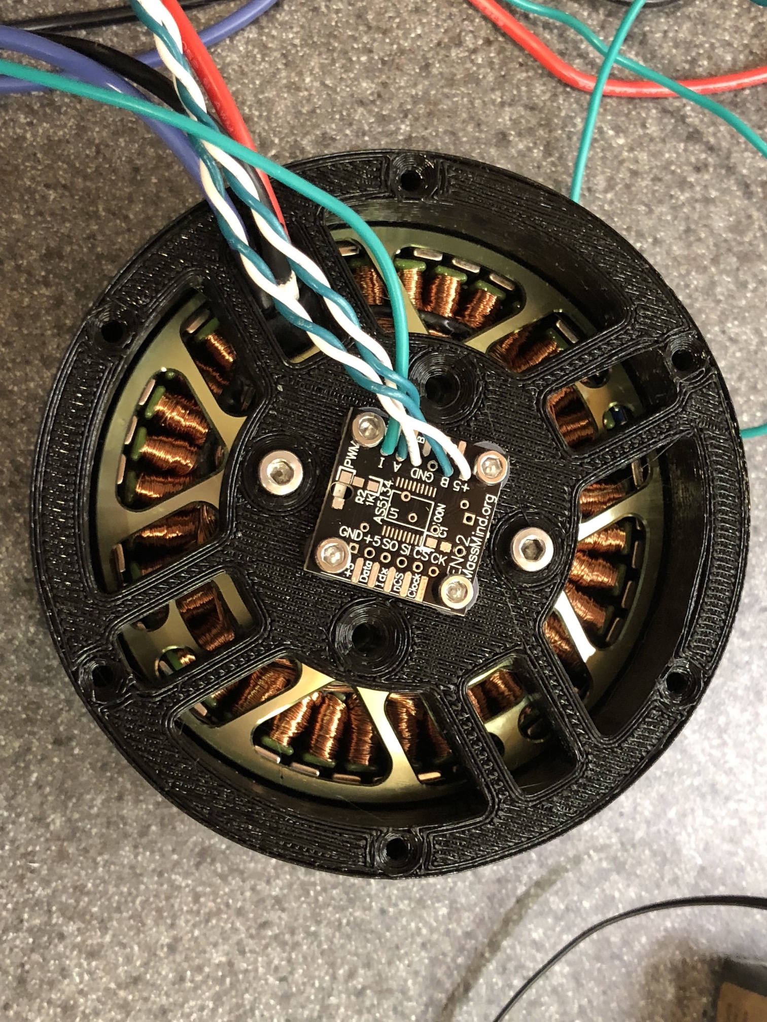
As an alternative to the expensive custom motors in the Cheetah, I’m using large off-the-shelf drone motors. The 8318 motor size produces enough torque and is relatively cheap. Hobbyking sells them rebranded as the Multistar 9235-100KV, which is what I’m using.
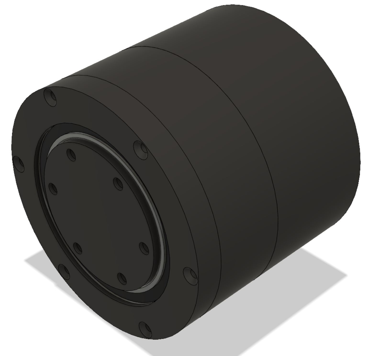
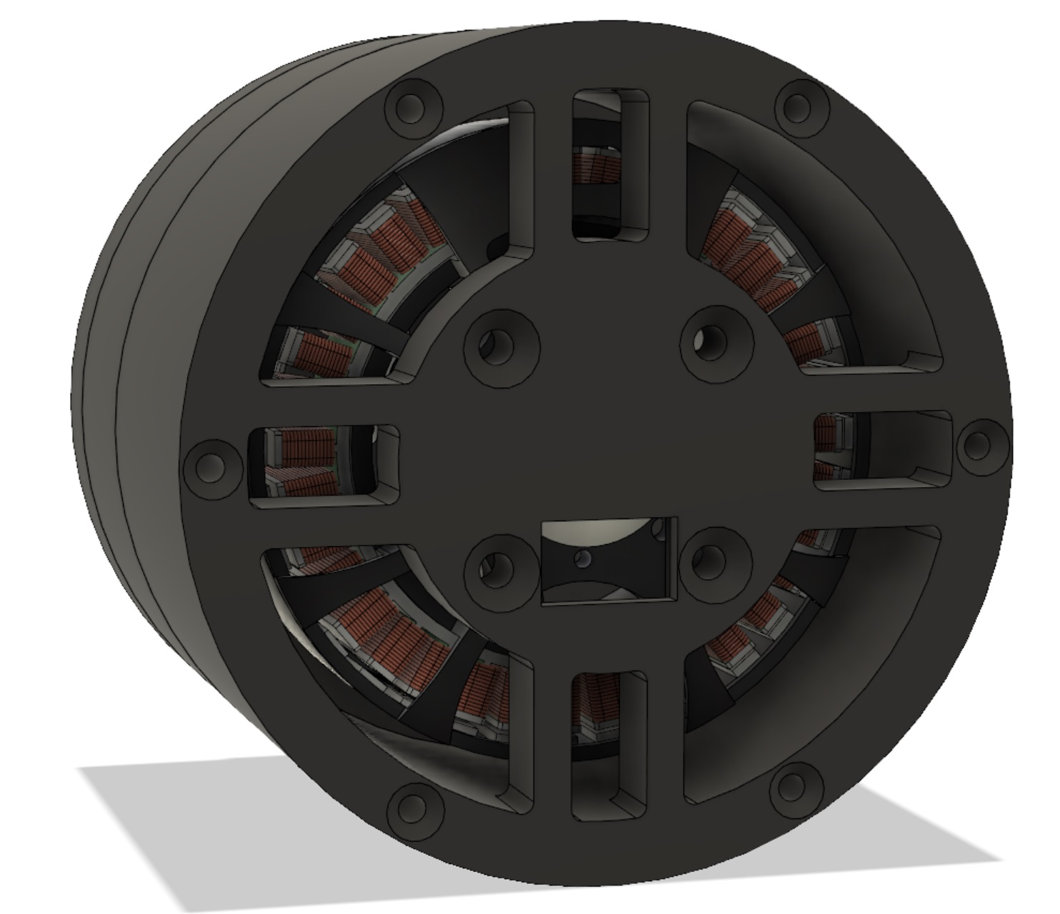
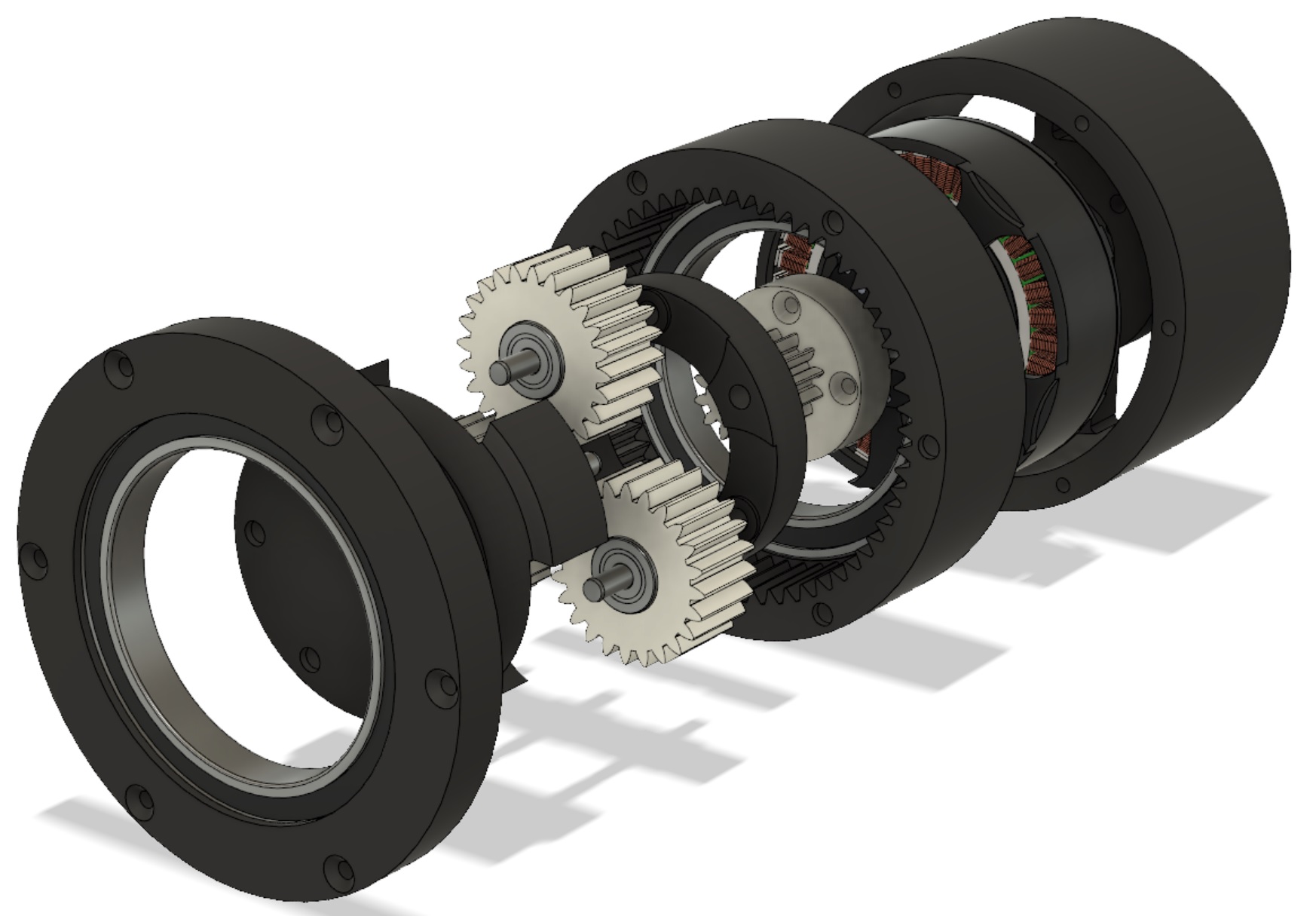
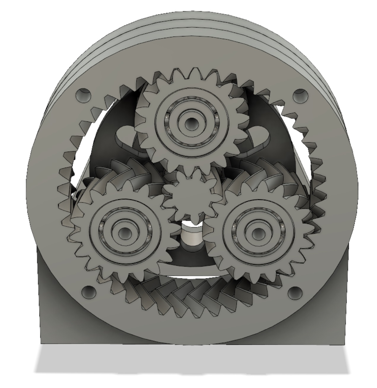
The current design: (The black parts will be printed in NylonX and the white ones in Alloy 910)
Here are the specs. I’ll take some real measurements once I get it put together.
28 Nm of torque (possibly higher for short bursts)
0.95 kg
6:1 gear ratio
Under $150 in materials
I’m going to open-source the design when I’m finished, since it seems like it would be useful to people. As far as I know there aren’t any off-the-shelf or DIY actuators that are lightweight, high torque, and compliant.
Here’s a paper explaining the concept of quasi-direct-drive in more detail:
where did you purchase the sunrise m2210e torque sensor and how much did it cost ?
you mention “noisy” planetary gear while printing? is it audio noise? mecanic noise ? how much? do you have an estimate or the gearbox efficiency? any backlash?
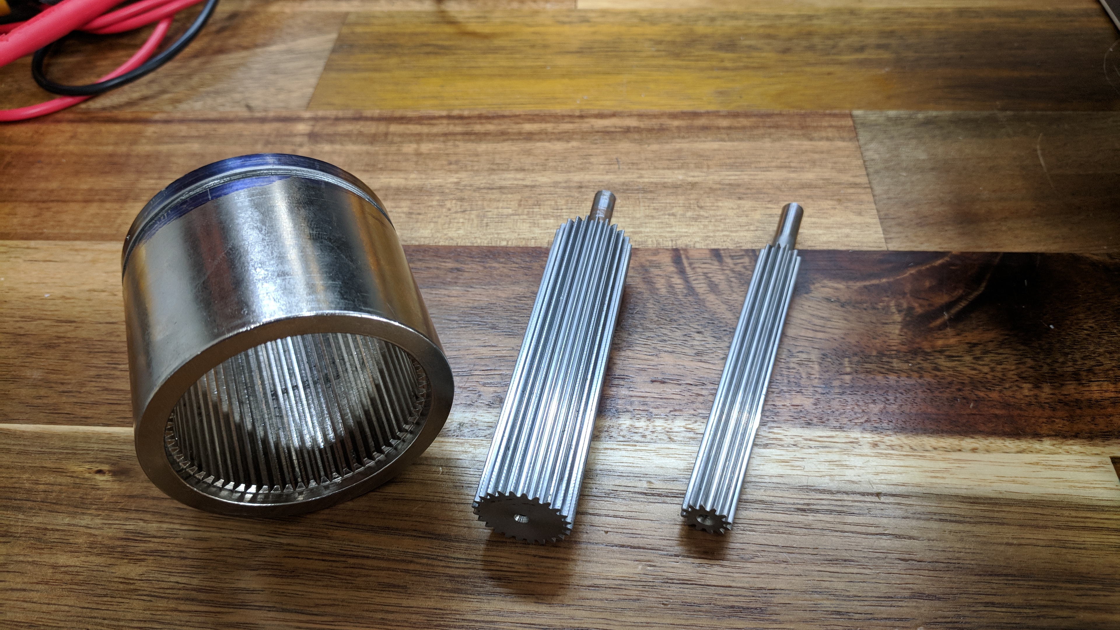
i faced difficulties with planetory gearboxes myself, even single stage. 3d printing in pla/abs would make it noisy, fragile or imprecise. i could only cnc mill 5mm height gears because the size of teeth made mandatory the use of a small (say 1mm) end mill in particular for the inside corners of internal teeth of the ring. such and endmill could cut very deep (typically 5mm). i could not calculate it but by intuition i could say that such a gearbox would not tolerate high loads.
it seems you favored v-like/twisted tooth profile. i am guessing to reduce friction. but it makes later machining much more complex. did you try to mill them yourself? would a 4th axis in a regular cnc mill + a lathe for making the center hole and finishing be enough?
I’m using the built-in current control mode on the ODrive for torque control, not an external torque sensor.
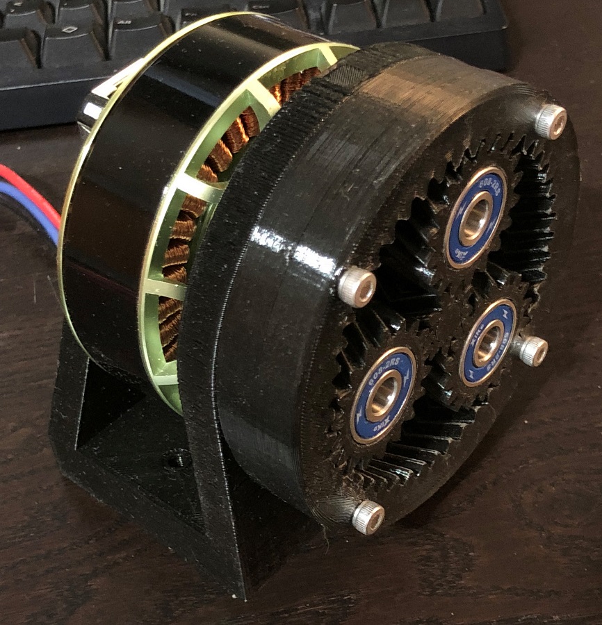
The printed PLA gears are audibly noisy. I’m mitigating this by switching to Nylon for the gear material, and increasing the number of teeth on every gear. This should help it run smoother.
I’m not too concerned with backlash, since accurate position control isn’t a priority for this application. With that said, the earlier prototype I made has very little backlash. I’ll have to see how much the backlash increases as the gears wear in.
The efficiency should be the same as any other single-stage planetary gearbox (95% or better).
Strength is definitely an issue for small plastic gears. I’m solving this by printing in Nylon instead of PLA or ABS and using thick gears (20mm). According to the mechanical stress simulation in Fusion 360, there should be a 3x margin of safety for a load of 10Nm on the sun gear (equal to 60Nm on the output). Hopefully this is enough to resist shock loads.
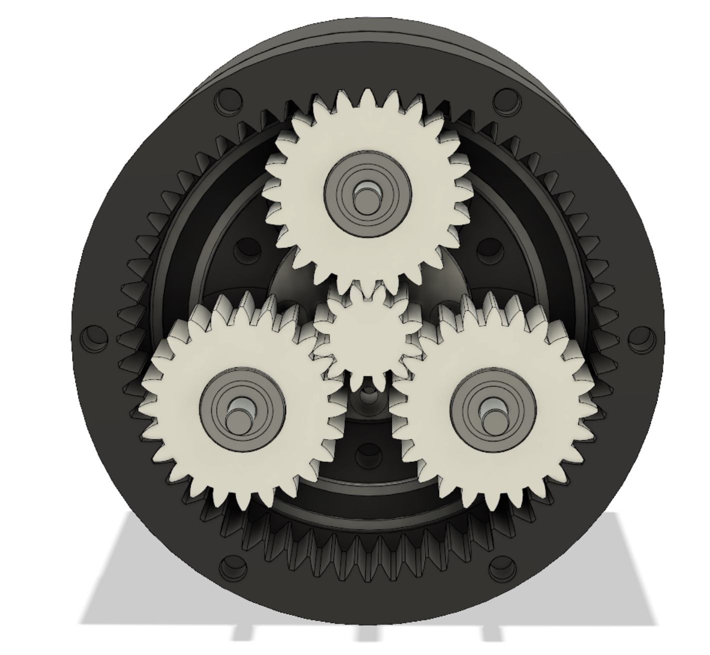
The v-shaped herringbone teeth are actually worse for efficiency because they introduce sliding friction. I only used them so the planet gears would self-retain themselves inside the ring gear. This next prototype I’m building uses normal spur gears. Here’s the old design and the new one compared:
i see.
I understand your model is not finished.
Can you nevertheless share with us the latest cad file for your planetary gear please?
i’m curious to see if i could milling with my own equipment of i would have to print it.
thanks
Nice compact design. One suggestion could be to add a fan enclosure just rear of the magnetic encoder and a few side vents between the motor and the gearbox. I would expect a 2 to 3x improvement in your usable (I.e. not overheating your motor) holding torque/current if you can get some air moving over the windings.
Since most of the parts are 3d printed I’m betting a large fraction of the total mass is coming from the big 6813 bearings used in this design. I understand that they are convenient to use due to their big boar diameter but they will of course be massively underutilised in this application. Although it would not be as compact you might be able to save a lot of weight by replacing the 6813’s with two smaller preloaded bearings up the front (after the gear reduction) in a spindle bearing type arrangement and leave the planet carrier back plate floating. Just a thought.
Awesome! This is literally exactly my plan for building an actuator for the same thing. Legged robotics. My plan is to CNC more of the components from metal but other than that this is pretty it. Did you get some inspiration from Ben Katz on his build it’s blog? I also plan on using slightly larger t-motors but I will for sure be checking out your design. Very nice! Also in the future I really would love to have the actual motor controller integrated too. That would make it super plug and play for a more general audience. I’m getting my lathe up and running now and should have my gear box done very soon. Look forward to sharing and maybe we can even collaborate.
Thanks for the feedback, everyone. Yeah, I’m definitely adding a cooling fan. I’m thinking about writing some custom code in the ODrive firmware to take a moving average of the motor current, and using that to control the fan speed through the GPIO pins.
Yep. Ben Katz is awesome. The integrated motor driver board he built is what I hope the 1-axis ODrive will be like.
My ultimate goal for this project is to build 10 of these actuators to make a biped similar to Cassie, but that’s a while off in the future.
Got a few of these from SDP/SI. I’m hoping to bore these out and part out my gear components. You’ve given me some hope that for prototyping with 3D prints for the housing and carrier might work alright.
I need to go back and read kalouche again but I am hoping to do what he proposed with the duty cycle limiting. I forget the exact details but it seemed very reasonable to implement. I’m also hoping to get a thermistor in the windings if possible.
Check out “timing pulley stock”. Then you can just part if of to a desired height. They already come in lots of gear profiles. From there you just need to find a compatible ring gear which is also reasonable to find. Check banebots has lots of parts for this also.
I don’t know if this is actually possible (I’m not an EE), but maybe you could measure the motor temperature by keeping track of changes in the winding resistance.
Which T-Motors are you using? These Multistar motors are about the same size as the U10.
The motors sold on ODrive’s shop already have termistors in the windings, so we’ll be adding support for integrating sensing that pretty soon. If you are not using UART, there is no pin conflicts to also implement fan control in the ODrive.
The secondary option is probably model based fan speed based on filtered motor current, like you suggest. I wouldn’t suggest looking at the motor resistance, the change is too small compared to all the other voltages going around.