If you haven’t seen this already, here’s a seminar by the founder of Agility Robotics (the company that built Cassie) about the hardware and controls for walking. They’re using series-elastic actuators with real springs, but you could get it to work for direct- or quasi-direct-drive actuators by programming them to act like springs.
Apparently the efficiency of spur gears and helical gears is about the same according to this source. However its not clear from the book if this is only true for systems that are well lubricated and so this may not be true for your situation.
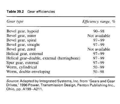
Still, if you end up sticking with 3D printed gears it may be worth comparing the efficiency at some point. If the herringbone design is roughly the same efficiency then it would make sense to stick with that design due to its other advantages like lower noise, higher load capacity, less backlash etc.
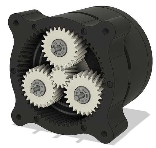
Interesting. I didn’t like the herringbone gears since they complicated the assembly process and required splitting the ring gear into 2 parts, but a helical gear could be a good compromise.
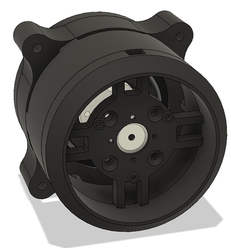
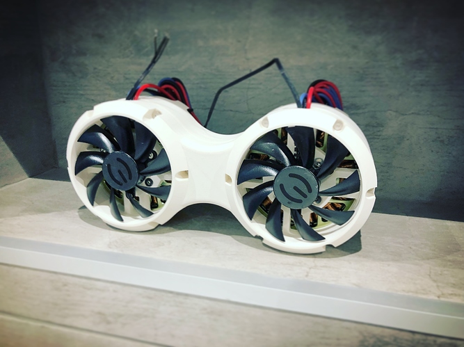
Updated the design with helical gears and active cooling. The duct on the back is sized for one of these frameless cooling fans: https://www.amazon.com/PLA09215B12H-GeForce-GTX760-TiTANX-Graphics/dp/B01M65LJFT
Here’s the STEP file: https://drive.google.com/open?id=1iAIbOn_ztodxXoGs9c7sHcxVPcMHvLLC
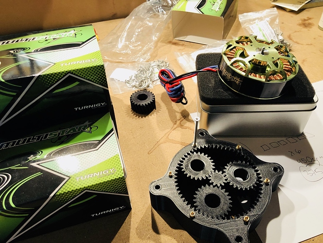
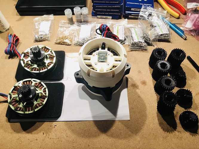
Finished printing everything out and assembled it. Now it’s time to run some tests.
I’m going to put a thermistor in the windings and see how much current it can take before overheating. I think it can plausibly take 120 amps of peak current thanks to the cooling fan.
Is it safe to put 120 amps through the MOSFETs? I assume I should put a cooling fan on the board, too.
I think 120 should be safe for short bursts. You need to turn up the motor.config.requested_current_range to 120A for the current sense amplifier gain range to let you go that high.
Yes put a fan to the board and keep an eye on the fet temps. Do you have a thermal camera?
Hi, I am doing electronics and firmware for the same purpose. I have done something like this before, a single stage 1/4-1/5 gear ration cyclic reduction, and later some timing belt based harmonic reduction. Now I hope to join you with your project as Open source development in electronics.
I made a video showing off some of the features:
STLs, BOM, and assembly instructions coming soon.
Great potential to do the equivalent to ANYmal robot drive:
Have you begin ROS integration? Looks like OD has no working ROS drive on web i could find at the moment.
What’s involved in making it work with ROS? I’m going to make a physics model for use in OpenAI/Mujoco reinforcement learning, and I think you could easily import that model into ROS.
Ahh, I see. I thought you will use this motor as a ROS node to test manipulation trajectory.
I set up a Hackaday page for this project. Follow here for future updates:
This seems like an great fun project! Great work @g-levine
Just got 10pcs of the Turnigy Multistar 9235-100KV and have started printing the parts for the Actuators
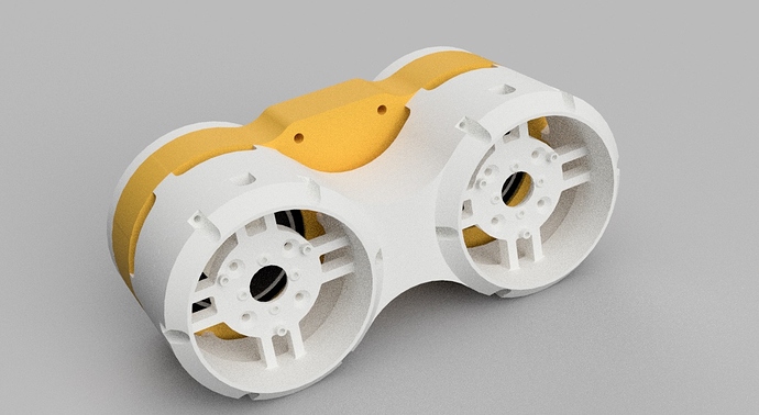
A modified dual version for a hip joint
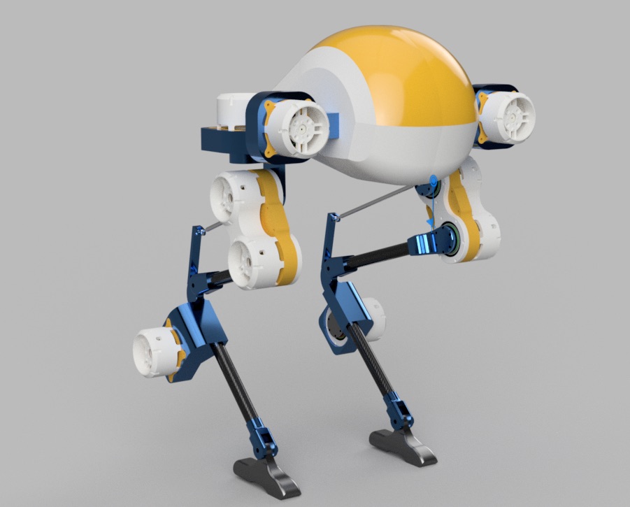
I have started sketching on a body based on how Cassie is designed
/RF
bad ass robocop ED-209 
The aesthetics of these are sick af, looks super awesome.
This project looks totally amazing, can’t wait to see it keep going!
