Hoverboard Motor Calibration Issues

I have five ODrives and can’t get a Hoverboard Motor working or even calibrated.
After extensive tries, updating, refreshing and assuring the hardware is fine, here is my general issues:

Operating System macOS Big Sur
odrivetool Version v0.5.4
Firmware Version v0.5.4
ODrive Version V3.6 56V
ODrive Number (personal) 3
Powersupply MEAN WELL 12V 22A
Motor Hoverboard
Motor Number (personal) 1
Axis Number 0

  • After following the hoverboard tutorial the Odrive doesn’t appear after rebooting from terminal
    • Powercycling makes it appear
  • AXIS_STATE_MOTOR_CALIBRATION only makes the motor beep
    • error: 0 (uint64)
    • phase_inductance: 0.0003140495391562581 (float)
    • phase_resistance: 0.20403261482715607 (float)
  • AXIS_STATE_ENCODER_HALL_POLARITY_CALIBRATION makes the motor spin in one direction
    • error: 16 (uint16)
  • AXIS_STATE_ENCODER_OFFSET_CALIBRATION does nothing
    • error: 528 (uint16)

Lets try to refresh the firmware!

  • odrivetool dfu (DIP switch on RUN)
    • 16:27:28.777217 [LEGACY_PROTOCOL] received unexpected ACK: 218
  • Powercylce doesn’t help
  • After multiple powercylces and unplugging the USB connection the ODrive was found
    ODrive control utility v0.5.4
    Waiting for ODrive…
    Found ODrive 335B314C3536 (v3.6-56V) with firmware v0.5.4
    Checking online for newest firmware… found v0.5.4

You are about to flash firmware v0.5.4 which is the same version as the firmware on the device (v0.5.4).
Do you want to flash this firmware anyway? [y/N] y
Downloading firmware v0.5.4…
Saving configuration to /var/folders/c5/f9jyw7ms6hl4j590tqg6k9vw0000gn/T/odrive-config-335B314C3536.json…
The file /var/folders/c5/f9jyw7ms6hl4j590tqg6k9vw0000gn/T/odrive-config-335B314C3536.json already exists. Do you want to override it? [Y/n] Y
Configuration saved.
Putting device 335B314C3536 into DFU mode…
Erasing… done
Flashing… (sector 6/7)
Traceback (most recent call last):
File “/usr/local/bin/odrivetool”, line 149, in
odrive.dfu.launch_dfu(args, logger, app_shutdown_token)
File “/usr/local/lib/python3.9/site-packages/odrive/dfu.py”, line 512, in launch_dfu
update_device(device, firmware, logger, cancellation_token)
File “/usr/local/lib/python3.9/site-packages/odrive/dfu.py”, line 434, in update_device
dfudev.write_sector(sector, data)
File “/usr/local/lib/python3.9/site-packages/odrive/dfuse/DfuDevice.py”, line 216, in write_sector
self.write(blocknum, block)
File “/usr/local/lib/python3.9/site-packages/odrive/dfuse/DfuDevice.py”, line 108, in write
return self.dnload(block + 2, data)
File “/usr/local/lib/python3.9/site-packages/odrive/dfuse/DfuDevice.py”, line 62, in dnload
cnt = self.control_msg(DFU_REQUEST_SEND, DFU_DNLOAD, blockNum, list(data))
File “/usr/local/lib/python3.9/site-packages/odrive/dfuse/DfuDevice.py”, line 56, in control_msg
return self.dev.ctrl_transfer(requestType, request, value, self.intf.bInterfaceNumber, buffer, timeout=timeout)
File “/usr/local/lib/python3.9/site-packages/usb/core.py”, line 1082, in ctrl_transfer
ret = self._ctx.backend.ctrl_transfer(
File “/usr/local/lib/python3.9/site-packages/usb/backend/libusb1.py”, line 893, in ctrl_transfer
ret = _check(self.lib.libusb_control_transfer(
File “/usr/local/lib/python3.9/site-packages/usb/backend/libusb1.py”, line 604, in _check
raise USBError(_strerror(ret), ret, _libusb_errno[ret])
usb.core.USBError: [Errno 5] Input/Output Error
user@Users-MacBook-Pro ~ %

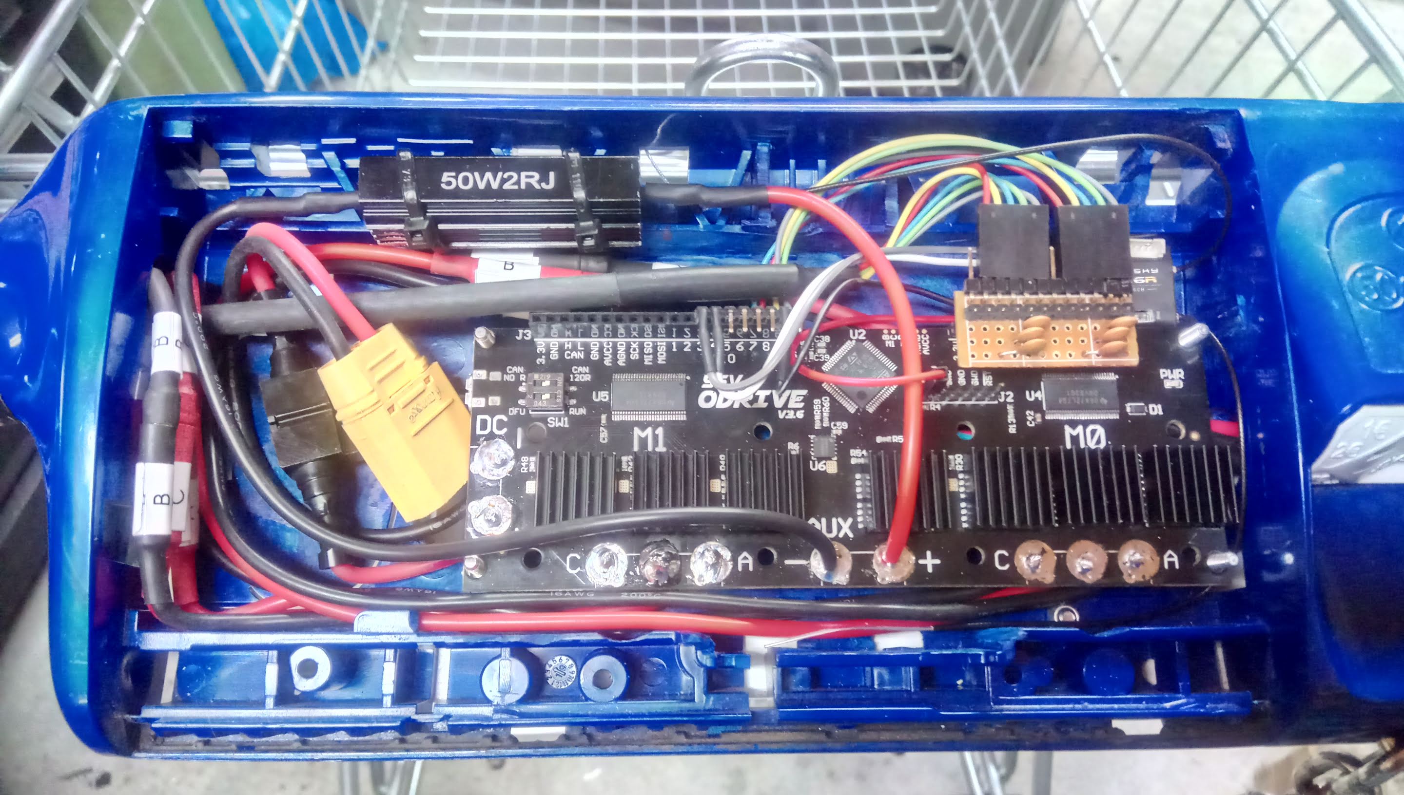
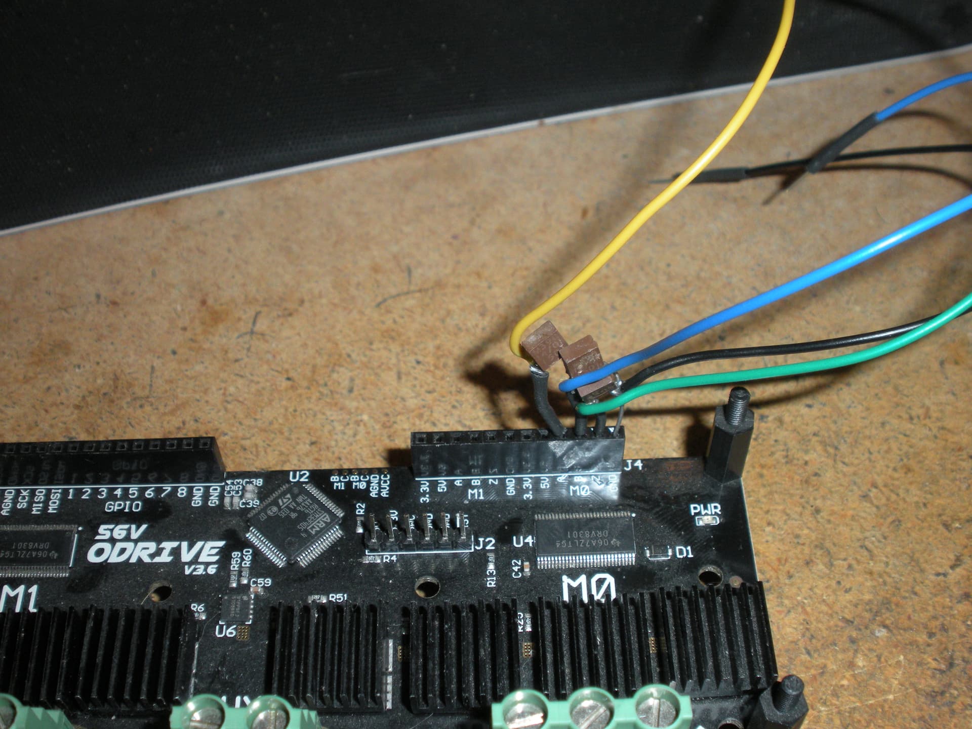
Here is my hardware setup:

So how should I proceed to get my ODrives working properly?

Thanks in advance!
Marv

I also have two odrive boards and I can’t get the hoverboard motors to work.
Could they write a better step by step or add more information on how to do it, errors that happen, general explanations?

Marv,
I was having a bunch of errors also until I added the 22nf caps to hall sensor inputs. My approach was to put them on the cable input. odrive_22nf_front|666x500 Less chance to damage Odrive.!
I looked at your picture again and it looks like the hall sensor is M1 and the drive voltage is M0??

1 Like

It definitely looks like the hall sensor wires are on the wrong pins. That would explain the error after calibrating the hall polarity.

I also had to add the 22nf capacitators (well, actually only one motor gave me trouble whilst calibrating, but I put them on both for good measure). I used a piece of prototyping board an a couple of header pins:

This video helped me a lot with visualising what should be happening whilst calibrating the motors: https://youtu.be/9UxTPxgvOAA

Here’s what I did to calibrate my hoverboard motors. Please note that I was using them with an RC controller (velocity control), so the values for vel_gain and vel_integrator_gain differ from those when using position control)

General settings:

odrv0.axis0.motor.config.current_lim = 40

odrv0.axis1.motor.config.current_lim = 40

odrv0.config.enable_brake_resistor = True

To calibrate axis 0:

odrv0.axis0.motor.config.pole_pairs = 15

odrv0.axis0.motor.config.resistance_calib_max_voltage = 4

odrv0.axis0.motor.config.requested_current_range = 25

odrv0.save_configuration()

odrv0.reboot()

odrv0.axis0.motor.config.current_control_bandwidth = 100

odrv0.axis0.motor.config.torque_constant = 0.516875

odrv0.axis0.encoder.config.mode = ENCODER_MODE_HALL

odrv0.axis0.encoder.config.cpr = 90

odrv0.axis0.encoder.config.calib_scan_distance = 150

odrv0.config.gpio12_mode = GPIO_MODE_DIGITAL

odrv0.config.gpio13_mode = GPIO_MODE_DIGITAL

odrv0.config.gpio14_mode = GPIO_MODE_DIGITAL

odrv0.axis0.encoder.config.bandwidth = 100

odrv0.axis0.controller.config.pos_gain = 1

odrv0.axis0.controller.config.vel_gain = 2.0

odrv0.axis0.controller.config.vel_integrator_gain = 0

odrv0.axis0.controller.config.vel_limit = 10

odrv0.axis0.controller.config.control_mode = CONTROL_MODE_VELOCITY_CONTROL

odrv0.save_configuration()

odrv0.reboot()

odrv0.axis0.requested_state = AXIS_STATE_MOTOR_CALIBRATION

odrv0.axis0.motor

odrv0.axis0.motor.config.pre_calibrated = True

odrv0.axis0.requested_state = AXIS_STATE_ENCODER_HALL_POLARITY_CALIBRATION

odrv0.axis0.encoder

odrv0.axis0.requested_state = AXIS_STATE_ENCODER_OFFSET_CALIBRATION

odrv0.axis0.encoder

odrv0.axis0.encoder.config.pre_calibrated = True

odrv0.save_configuration()

odrv0.reboot()

To test axis 0:

odrv0.axis0.requested_state = AXIS_STATE_CLOSED_LOOP_CONTROL

odrv0.axis0.controller.input_vel = 2

odrv0.axis0.controller.input_vel = 0

odrv0.axis0.requested_state = AXIS_STATE_IDLE

To calibrate axis 1:

odrv0.axis1.motor.config.pole_pairs = 15

odrv0.axis1.motor.config.resistance_calib_max_voltage = 4

odrv0.axis1.motor.config.requested_current_range = 25

odrv0.save_configuration()

odrv0.reboot()

odrv0.axis1.motor.config.current_control_bandwidth = 100

odrv0.axis1.motor.config.torque_constant = 0.516875

odrv0.axis1.encoder.config.mode = ENCODER_MODE_HALL

odrv0.axis1.encoder.config.cpr = 90

odrv0.axis1.encoder.config.calib_scan_distance = 150

odrv0.config.gpio9_mode = GPIO_MODE_DIGITAL

odrv0.config.gpio10_mode = GPIO_MODE_DIGITAL

odrv0.config.gpio11_mode = GPIO_MODE_DIGITAL

odrv0.axis1.encoder.config.bandwidth = 100

odrv0.axis1.controller.config.pos_gain = 1

odrv0.axis1.controller.config.vel_gain = 2.0

odrv0.axis1.controller.config.vel_integrator_gain = 0

odrv0.axis1.controller.config.vel_limit = 10

odrv0.axis1.controller.config.control_mode = CONTROL_MODE_VELOCITY_CONTROL

odrv0.save_configuration()

odrv0.reboot()

odrv0.axis1.requested_state = AXIS_STATE_MOTOR_CALIBRATION

odrv0.axis1.motor

odrv0.axis1.motor.config.pre_calibrated = True

odrv0.axis1.requested_state = AXIS_STATE_ENCODER_HALL_POLARITY_CALIBRATION

odrv0.axis1.encoder

odrv0.axis1.requested_state = AXIS_STATE_ENCODER_OFFSET_CALIBRATION

odrv0.axis1.encoder

odrv0.axis1.encoder.config.pre_calibrated = True

odrv0.save_configuration()

odrv0.reboot()

To test axis 1:

odrv0.axis1.requested_state = AXIS_STATE_CLOSED_LOOP_CONTROL

odrv0.axis1.controller.input_vel = 2

odrv0.axis1.controller.input_vel = 0

odrv0.axis1.requested_state = AXIS_STATE_IDLE

To set up RC PWM

odrv0.config.gpio3_mode = GPIO_MODE_PWM

odrv0.config.gpio3_pwm_mapping.min = -2

odrv0.config.gpio3_pwm_mapping.max = 2

odrv0.config.gpio3_pwm_mapping.endpoint = odrv0.axis1.controller._input_vel_property

odrv0.config.gpio4_mode = GPIO_MODE_PWM

odrv0.config.gpio4_pwm_mapping.min = -2

odrv0.config.gpio4_pwm_mapping.max = 2

odrv0.config.gpio4_pwm_mapping.endpoint = odrv0.axis0.controller._input_vel_property

odrv0.save_configuration()

odrv0.reboot()

To start in closed loop state:

odrv0.axis0.config.startup_closed_loop_control = True

odrv0.axis1.config.startup_closed_loop_control = True

odrv0.save_configuration()

odrv0.reboot()

*Note that after setting the Odrive to start in closed loop state, you need to set all axes to be in IDLE if you want to make changes to the setup afterwards (this is for safety):
odrv0.axis0.requested_state = AXIS_STATE_IDLE
odrv0.axis1.requested_state = AXIS_STATE_IDLE

Hope this helps.

1 Like

We think there is a bug in the HALL_POLARITY checks. Set hall_polarity_calibrated = True before doing all the steps. Otherwise, should work out of the box. And yes, @Marv you have the halls plugged into the wrong channel :wink:

1 Like

Guys! It works! totally was the fault of the encoder not being connected in combination with the hall_polarity_calibrated = True and enable_brake_resistor = True!

Thank you so much for your help!

1 Like

One other issue… Even tho I can now make the motor spin the “odrv0.axis0.requested_state = AXIS_STATE_CLOSED_LOOP_CONTROL” doesn’t make it hold its position…(I mean it does for a lillte with almost no torque with overkill current limits) Position controls work neither and sometimes “odrv0.axis0.controller.input_vel = x” doesn’t get pushed to the board/motor…

system: no error
axis: no error
motor: Error(s):
MOTOR_ERROR_UNKNOWN_TORQUE
MOTOR_ERROR_UNKNOWN_VOLTAGE_COMMAND
sensorless_estimator: no error
encoder: Error(s):
ENCODER_ERROR_ILLEGAL_HALL_STATE
controller: no error

Anything I’m missing here?

You basically won’t get it to hold position with hall sensors. If you’re getting illegal hall state in closed loop, you may need to add filtering to the ABZ pins, or you may genuinely have a hall state problem on that motor

1 Like

Try putting it into closed loop torque mode at zero torque, and then carefully rotate the wheel by hand a few rotations, do you get the Hall state error?

If you don’t get any Hall state errors at zero torque, but you do when you increase the torque, then it is a noise issue. Try the ferrite rings on the motor wires, and/or add capacitors (~22nF) to GND on each of the A/B/Z (U/V/W) pins.

1 Like

Hello,

Thanks for this guide. I am currently having some problems to get my hoverboard motor spin. I just got my Odrive motor driver yesterday, 56V V3.6. I have followed this calibration process here and from the Odrive website here
However, after I activated the motor calibration, and checking the data pertaining to the motor, I got the following error:
error: 0 (uint64)

This is the result:

In [16]: odrv0.axis0.motor
Out[16]:
DC_calib_phA: 0.7796252965927124 (float)
DC_calib_phB: -0.1720525622367859 (float)
DC_calib_phC: -0.6076174974441528 (float)
I_bus: 0.0 (float)
config:
I_bus_hard_max: inf (float)
I_bus_hard_min: -inf (float)
I_leak_max: 0.10000000149011612 (float)
R_wL_FF_enable: False (bool)
acim_autoflux_attack_gain: 10.0 (float)
acim_autoflux_decay_gain: 1.0 (float)
acim_autoflux_enable: False (bool)
acim_autoflux_min_Id: 10.0 (float)
acim_gain_min_flux: 10.0 (float)
bEMF_FF_enable: False (bool)
calibration_current: 10.0 (float)
current_control_bandwidth: 100.0 (float)
current_lim: 10.0 (float)
current_lim_margin: 8.0 (float)
dc_calib_tau: 0.20000000298023224 (float)
inverter_temp_limit_lower: 100.0 (float)
inverter_temp_limit_upper: 120.0 (float)
motor_type: 0 (uint8)
phase_inductance: 0.0003897541027981788 (float)
phase_resistance: 0.23592844605445862 (float)
pole_pairs: 15 (int32)
pre_calibrated: True (bool)
requested_current_range: 25.0 (float)
resistance_calib_max_voltage: 4.0 (float)
torque_constant: 0.5168750286102295 (float)
torque_lim: inf (float)
current_control:
I_measured_report_filter_k: 1.0 (float)
Ialpha_measured: 0.0 (float)
Ibeta_measured: 0.0 (float)
Id_measured: 0.0 (float)
Id_setpoint: 0.0 (float)
Iq_measured: 0.0 (float)
Iq_setpoint: 0.0 (float)
Vd_setpoint: 0.0 (float)
Vq_setpoint: 0.0 (float)
final_v_alpha: 0.0 (float)
final_v_beta: 0.0 (float)
i_gain: 23.592845916748047 (float)
p_gain: 0.03897541016340256 (float)
phase: 0.0 (float)
phase_vel: 0.0 (float)
power: 0.0 (float)
v_current_control_integral_d: 0.0 (float)
v_current_control_integral_q: 0.0 (float)
current_meas_phA: -0.7788164615631104 (float)
current_meas_phB: 0.17181989550590515 (float)
current_meas_phC: 0.606977105140686 (float)
effective_current_lim: 10.0 (float)
error: 0 (uint64)
fet_thermistor:
config: …
temperature: 28.237287521362305 (float)
is_armed: False (bool)
is_calibrated: True (bool)
last_error_time: 0.0 (float)
max_allowed_current: 30.375 (float)
max_dc_calib: 3.0375001430511475 (float)
motor_thermistor:
config: …
temperature: 0.0 (float)
n_evt_current_measurement: 885417 (uint32)
n_evt_pwm_update: 885419 (uint32)
phase_current_rev_gain: 0.012500000186264515 (float)

I went ahead with the calibration process. when I executed this command
In [30]: odrv0.axis0.requested_state = AXIS_STATE_ENCODER_HALL_POLARITY_CALIBRATION
to check the alignment between the motor and the hall sensors, my motor spun in one direction and stop.

However, I checked the status of the encoder and I got the following error:
error: 528 (uint16)

In [22]: odrv0.axis0.encoder
Out[22]:
calib_scan_response: 0.0 (float)
config:
abs_spi_cs_gpio_pin: 1 (uint16)
bandwidth: 100.0 (float)
calib_range: 0.019999999552965164 (float)
calib_scan_distance: 150.0 (float)
calib_scan_omega: 12.566370964050293 (float)
cpr: 90 (int32)
direction: 0 (int32)
enable_phase_interpolation: True (bool)
find_idx_on_lockin_only: False (bool)
hall_polarity: 0 (uint8)
hall_polarity_calibrated: False (bool)
ignore_illegal_hall_state: False (bool)
index_offset: 0.0 (float)
mode: 1 (uint16)
phase_offset: 0 (int32)
phase_offset_float: 0.0 (float)
pre_calibrated: False (bool)
sincos_gpio_pin_cos: 4 (uint16)
sincos_gpio_pin_sin: 3 (uint16)
use_index: False (bool)
count_in_cpr: 0 (int32)
error: 528 (uint16)
index_found: False (bool)
is_ready: False (bool)
phase: 0.0 (float)
pos_abs: 0 (int32)
pos_circular: 0.0 (float)
pos_cpr_counts: 0.0 (float)
pos_estimate: 0.0 (float)
pos_estimate_counts: 0.0 (float)
set_linear_count(obj: object_ref, count: int32)
shadow_count: 0 (int32)
spi_error_rate: 0.0 (float)
vel_estimate: 0.0 (float)
vel_estimate_counts: 0.0 (float)

I continued again with calibration till the last stage and my motor could not spin any more. My Hoverboard came with 6 wires hall sensor. The sixth wire was for temperature control. so, I did not connect it since there is no space for that in the Odrive motor board (J4 port). I connected 47nF capacitor each for the hall sense pin.

Can someone please help me on how to solve these problems. Sample code to get started with running the two motors would also be appreciated. I am super new to odrive, although I have a couple of projects that I was recommended to use odrive controllers.
Thank you in advance.

Please use dump_errors(odrv0) to check error codes, it’ll give you an english name for the error code.

Thank you for your reply. The error name is ILLEGAL_HALL_STATE

Try setting encoder.config.hall_polarity_calibrated = True and trying the steps again.