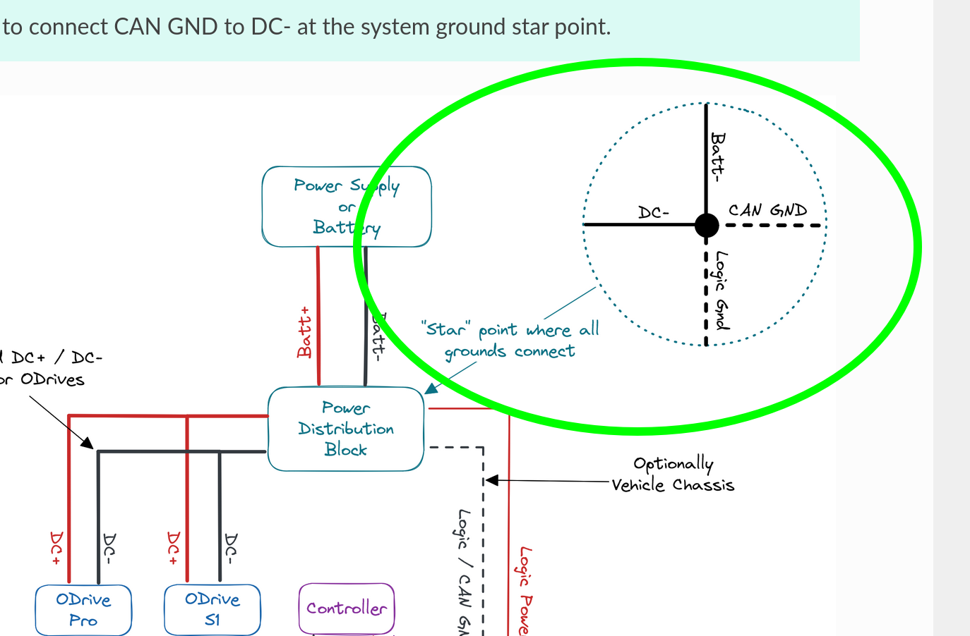
Hi! On the ODrive Micro and S1, CAN is referenced to the ODrive’s DC-, and the CAN connectors are just used for a convenient daisy-chain (the CAN GND is internally not connected, only passed between the connectors). On the ODrive Pro, CAN is referenced to CAN_GND (which must be connected to the system DC- at some point). Typically, you want to star logic and power grounds at a single location. In the Arduino docs, the passthrough CAN_GND is used as an easy way to get the Arduino on the same ground domain as the S1 – another option would be to just run a wire from Arduino GND to the S1 DC-, or preferably to do so near your power supply / battery / power distribution block. Note that it does show to connect grounds in the CAN bus guide:
I fully understand how to connect gnd, but my point is that there is inconsistency between the photo and the description. On the photo the CAN_GND is connected to DC- event though the description says that this is done internally on the S1 board. This is just to avoid more gnd-loops.
After moving from ESP32 and UART to Teensy and CAN it seems that the setup is more stable.