I think it's bricked

Probably too much detail, but not sure what’s relevant and what not…

I just got received a D5065 motor from the ODrive store a few days ago. Hooked it up to a clone single drive 3.5-48V drive with 48V SMPS and CUI encoder. I know, bad to buy the clone, but I don’t have space or use for the second axis - I would buy the official single drive if there were one, for reasons that may become clear.

Unfortunately, I forgot to order the connector for the encoder, and it took 7 days to get to me, so I messed with sensorless mode in the meantime. The motor did turn, possibly at the wrong speed. The ODrive seemed to be operational, though some oddities which I think were due to my misunderstanding about FW versions.

I got the connector for the encoder, hooked it up , reconfigured the ODrive and got an error ERROR_CPR_POLEPAIRS_MISMATCH and a high-pitched noise when calibrating. I checked the encoder DIP switch and the config settings: 8192 CPR and 7 pole pairs, which I think is right. At any rate, one turn of the motor shaft altered the encoder count by about 8192 counts. Wiring and grounding seems OK. I found the problem was in the encoder offset part of the full calibration, the earlier steps worked OK.

I couldn’t get much help online, and came to realize the clone FW it came with was not current, so decided to update it in the hopes that might get me somewhere. I ran odrivetool dfu in Linux and it seemed to “take”, but now the drive was stuck in initialization, I think. The requested state was 2 and the current state was 0, and none of the calibration commands worked, and the encoder counts didn’t increment.

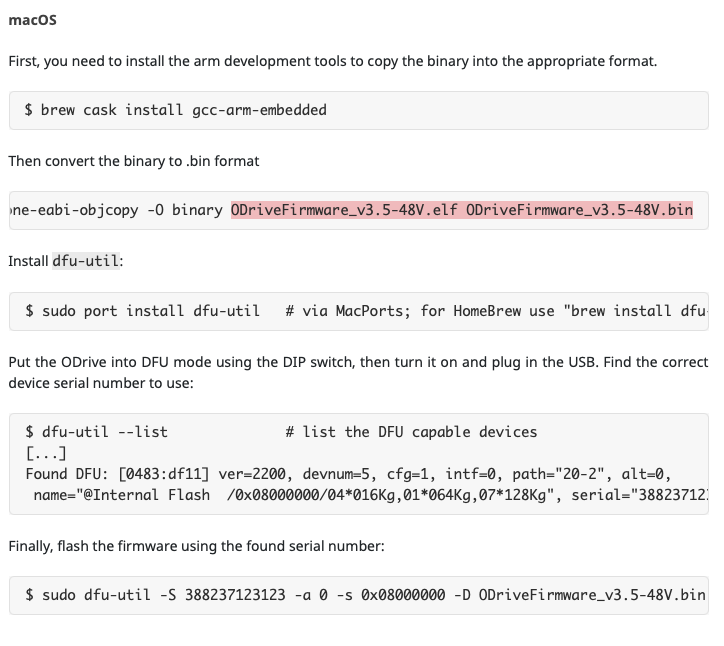
I retried this process a few times, including in Windows/anaconda, and it’s all a bit of a blur, but at some point I think I uploaded the wrong firmware version (3.6 possibly), or something else happened and the board does not have a version loaded (make write_otp is suggested) and the USB interface did not work (except the bootloader when I flip the DFU DIP switch). So I tried using dfu_util and that succeeded with the correct 3.5-48V version. However, still no USB interface, and odrivetool dfu still tells me the version is not loaded in the board. I am assuming my earlier DFU activities have munged up the OTP, and from the github comments it looks like there is no way I can get it back to a decent value, even if I knew how ( I haven’t found any noob-level instructions for this).

So is there some means to resurrect or at least make use of an ODrive that has a bad version in the OTP? Other than replacing the chip. And even if that is fixed, any ideas on getting the USB interface to work again?

My understanding is that the clone variants that are out in the wild contain some firmware hacks to deal with the fact that one axis is missing. In other words your board is probably failing its power on self-test and getting stuck somewhere. Unless you can find some firmware patch in the wild somewhere, you’re probably done for.

2 Likes

Thanks for the input. It could explain the inability to get out of state 2 with upgraded FW, but it doesn’t explain the earlier ERROR_CPR_POLEPAIRS_MISMATCH which was with the pre-loaded FW, or the current absence of the USB comm ( the only interface that ever appears in lsusb is the STM32 bootloader) or the corrupt OTP. I could try putting the old firmware back - if I could find it - and that MIGHT fix the USB problem, but I’d still have the ERROR_CPR_POLEPAIRS_MISMATCH in that FW to deal with, as well as the corrupt OTP in the hardware. That seems to be the end of it, unless there’s a FW hack to ignore it. It worries me a little that using the ODrive tools can brick the CPU chip…

It’s not bricking the OTP, it’s just stuck in an initialization loop waiting for the second axis to boot. This guy seems to have the same problem [SOLVED] New firmware & odrive tool v5.1 for 3.4-24v custom board, one axis Unfortunately we can’t support custom hardware further

The firmware is always recoverable via STLink, regardless of what happens with the Device Firmware Update bootloader.

I would suggest to ask the seller of the board to send you the modified firmware. Then you have two options:
Flashing with the DFU bootloader by pulling Boot0 to 3.3v and Boot 1 to GND.
Or
Flashing the MCU withe a debugging tool like a STLink

Of course you are correct. I now have the thing working with the latest from the development branch, and the OTP is as it should be. I bit the bullet and set up the build environment, with only a momentary (but very traumatic) setback when I installed git-all instead of git. I was going to apply the change you refer to, but I see that bit of code has just been changed to report an error on an axis that fails to respond, rather than just sitting there, so no changes were actually needed. Thank you to all the contributors.

Just to close the loop on this a little…

As I said, I did revive the single-axis clone, but it turns out that it’s useless as it has no brake resistor circuitry. That makes it completely unfit for use as a CNC spindle motor drive; it just alarms as soon as you reduce the speed. So let this be a warning to others. I am trying to get my money back under the “false description” clause, but not very hopeful.

In the meantime, I bought an official two-axis board for development. Hopefully a real single axis board will appear soon so I can fit it into my project. I am progressing pretty well and have a working Python script to provide enable and direction control via GPIO inputs to augment the analog speed control. The plan is to use it with LinuxCNC via a Mesa 7i76e spindle interface. Next is to try to migrate that into a LinuxCNC python HAL component. It’s pretty odd to have a PC use a USB interface to an embedded system to mediate between GPIO inputs and the firmware, but as far as I can tell there is no mechanism for GPIO digital inputs to control or be mapped so as to provide an enable or direction function in a way similar to the analog mapping function. If I may be allowed to say so, it strikes me as a serious omission, as this is possibly the most common spindle interface in the CNC world ( I mean an analog speed control with digital inputs for enable and direction - plus of course a buffered encoder output).

Ultimately, I will try to eliminate the USB interface by modifying the ODrive code or just use the USB via a LinuxCNC HAL component. Right now, I don’t know enough about either to guess which it will be. It looks like either would work, though the ODrive GPIO stuff looked scary at first glance, and there’s still the question of getting encoder data into LinuxCNC. Of course the best solution would be one someone’s already implemented - so anybody know of any such?

It’s an outstanding pull request:

Enable Pin PR: https://github.com/madcowswe/ODrive/pull/281
0-100% PWM Duty Cycle PR: https://github.com/madcowswe/ODrive/pull/292

Ah, good to know! Are you sure it’s analog? Or is it PWM duty cycle?

Well, yes. I am in the CNC repair business and many of the older drives that we still work on are 10V speed and discrete digital (24V usually) enable/direction. Plus some other digital inputs and outputs. Some were configurable for forward on and reverse on, rather than on and direction, but the 10V was pretty well universal. It was something of a de facto standard. For a while now data comm busses have been the control method of choice, but even there an OEM using multiple vendors might well use the standard 10V interface, since the data comm buss is usually proprietary. An example we worked on last week was a machine with FANUC control using 10V to control a Mitsubishi spindle drive. A FANUC spindle drive would have been controlled by a data interface. It had a spindle speed problem, and the problem turned out to be the power supply of the control. As a point of interest, both sides of the interface had parameters for adjusting the full scale (10V) speed and a zero speed offset voltage.

The analog interface is far from dead. I have a couple of new small Chinese BLDC controllers that both have analog inputs, with digital enable and direction inputs. One is 5V full scale and claims to have a PWM input also, but it’s probably just a low pass filter on the speed input. The other is 10V.

I don’t recall working on any industrial systems that use PWM. Of course, LinuxCNC and Mach3 both support PWM speed control, and there may be others for all I know.

I saw that pull request. I know virtually nothing about source control systems, or STM32 either, so a quick look into the enable-pin branch code only frightened me. Too steep of a learning curve right now, so I will probably have to do what I can on the LinuxCNC side and live with the USB interface.

If anyone is doing any work on that enable-pin branch, I’d put in a strong request for a direction pin also, and also for some form of encoder output, either GPIO pins or whatever, preferably scalable. That is vital for any kind of synchronized operation between axes, such as threading, mill-turn type operations, and constant surface speed machining. I have in mind a project like the SwissMak, for which the ODrive would be ideal.

Thanks for all the info! Always nice learning from knowledgeable folk :slight_smile:

I’m not sure what the blocker is for the enable pin. I’ll ask about these features and follow up with you.

do you still have this firmware handy? I’m trying to set up my own build environment for a single axis clone but lately I haven’t had time to sink on it.

@Wetmelon I have the same issue, I couldn’t get STM32 Cube programmer to work, and seems like in the Odrive documentation the DFU-until for Mac section is not updated for Odrive v3.6 56v board? I tried to change the file name to v3.6 56v and it says no such file.