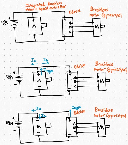
Hi everyone. I am working on a self-driving bicycle project and have some questions about power distribution/brushless motor control related to the odrive. I apologize if any of these questions are obvious.
I have two main components in the project: the ebike mid-drive motor, and a brushless motor used for gyroscopic stabilization. The gyroscope is the one powered by the odrive while I have no direct control over the bike motor. See the first diagram in the image.
So here are my questions:
-
How do I safely distribute power from a central battery to multiple motors/controllers? I don’t exactly know what I’m looking for and how to find the proper rating component. A power distribution board on amazon?. It doesn’t seem like a good idea to have a bunch of wires soldered together into a Y configuration.
-
Refer to the 2nd and 3rd diagrams in the image: Consider the situation where one of the motors are braking. Since the motor is slowing down, this would induce a back-emf which would normally be used for regenerative braking to recharge the battery. However, since the motors are in parallel, could this back-emf would this induce a current that enters the other motors in parallel (as well as the battery?) . How much of an issue would this pose?
Any insight is appreciated. Thanks!
Wonderful questions 
I have two main components in the project: the ebike mid-drive motor, and a brushless motor used for gyroscopic stabilization. The gyroscope is the one powered by the odrive while I have no direct control over the bike motor. See the first diagram in the image.
Wow, super cool!
- How do I safely distribute power from a central battery to multiple motors/controllers? I don’t exactly know what I’m looking for and how to find the proper rating component. A power distribution board on amazon?. It doesn’t seem like a good idea to have a bunch of wires soldered together into a Y configuration.
I have seen more “Y” soldered wires than you’d ever believe. It’s a bad solution for sure, but it works.
I generally don’t love the PCB style power distribution boards, just because they’re a bit low current (the copper on PCBs is pretty thin). That being said, it would work fine. I usually opt for a busbar, something like this (but there’s a lot of cheaper options).
- Refer to the 2nd and 3rd diagrams in the image: Consider the situation where one of the motors are braking. Since the motor is slowing down, this would induce a back-emf which would normally be used for regenerative braking to recharge the battery. However, since the motors are in parallel, could this back-emf would this induce a current that enters the other motors in parallel (as well as the battery?) . How much of an issue would this pose?
When braking, the ODrive will regenerate power onto the DC bus in the form of current. If the total current regenerated is greater than the current being drawn by the motor, then it’ll recharge the battery. Not an issue whatsoever – intended behavior! The other motor+esc should handle this just fine, the battery voltage will maybe raise by a few hundred mV but nothing that will cause issues.
Hi thank you so much for your response! Things are a lot more clear now. Just to make sure I’m getting it, the motor controller only draws current when the motor is under load, so the majority of the extra current from the back-emf travels back into the battery. Is this right?
And do you have any recommendations for resources on brushless controller design/theory? I’m thinking of making a diy controller for learning purposes at some point since I don’t entirely understand how they work (hence my question).
Thanks again!
Great to hear!
the motor controller only draws current when the motor is under load, so the majority of the extra current from the back-emf travels back into the battery. Is this right?
Mostly correct – back-emf and regenerated current are two different things – back-emf only refers to the motor’s generated voltage when spun and is always (not always but for the purposes of this, always) lower than the DC bus voltage. It’s the ODrive control algorithm that actually regenerates the motor’s mechanical power onto the bus in the form of electrical energy.
BLDC control is tricky, but a lot of fun! I recommend looking at TI and ST reference designs for the hardware side (and the ODrive v3.6 design – it’s open source), and James Mevey’s masters thesis for the theory/control side.
