Hi all! I am trying to control a PMSM in speed mode and analyze the power consumption over different operating points using an oscilloscope. My Vdc is 48V, and the motor is delta configured. In fact, I can control the motor and follows the reference speed perfectly, but the voltage signals generated by the inverter are kinda confusing to me.
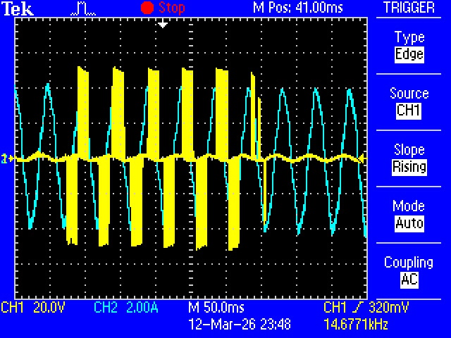
Here, for instance, I show a picture of my oscilloscope. In yellow, the voltage between 2 phases of the inverter (hence terminals A & B of my motor). At the begining we can clearly see a sinusoidal PWM, with the correct electrical frequency (motor spinning at 250rpm and 5 pole pairs, so fe=250/60*5=20.8Hz, T=50ms). But then the PWM turns off, I can’t understand why. Furthermore, the current (in cyan) is unbothered. This behaviour repeats periodically over time.
Can anyone elaborate on this behaviour? Is it normal?
Thanks in advance!
.jpeg)
Hi! So the oscilloscope is connected with the GND lead on one phase, and the probe tip connected to another phase? That’s going to make the scope ground swing all over the place with reference to the ODrive’s DC-. If the ODrive is on a power supply, or there’s a ground loop of some kind (even just coupling through the power supply’s y-capacitors), it could be causing a lot of current draw through the scope / GND lead – I almost wonder if you’re blowing a fuse in the scope or something. Usually what I’d recommend is to use an actual differential probe (I use the Micsig DP1500), or to use two scope channels with probes grounded to DC- and connected to e.g. phase A/B, using the scope’s math channel to subtract them to get the relative voltage.
Hi! I’m actually using a differential probe (ELDITEST GE 8100). It seems to work correctly for every other test I’ve done so far. I connect one lead to Output A of the Odrive and another one to Output B. So I should be correctly measuring floating Line-Line voltages.
To describe a little bit better my setup, I have a test motor connected to a load motor. The load motor sets the load torque (via another controler). The test motor is speed controlled via an Odrive S1.
Oh gotcha, that’s great then, thanks for the info.
This looks like a… TDS2022C or similar? Could this be memory depth issues on the scope? Quick search shows 2.5Kpts/channel, if you’re capturing a 10*50ms = 500ms window, that’s a max sample rate of 2500/0.5 = 5kHz. I’d hazard a guess that as the modulation is getting lower, it’s just missing the (much more narrow) pulses. You could try using “peak detect” sampling mode on the scope, but I still don’t know if that would be a fix. Is there another scope you could try using?
You seem to be completely right! The record length is way too limited to capture the PWM signal, given that the switching freq of the Odrive S1 is 24kHz.
In the pictue below, with “peak detect” (as you sugested) and same time escale, the PWM signal is captured. Good to know it does not magically disapear as in the original post!
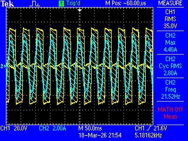
However find hard to believe that in my original post the PWM signal disapears because the modulation gets lower. Why would the modulation get that low if I’m running my motor at constant speed? It would be slightly modified by the controller to maintain the speed constant, but not that much. I would bet it has to do with the oscilloscope itself.
Anyways, this is the only oscilloscope I have so I will have to measure the power of the motor differently. Do you think odrv.axis0.motor.electrical_power is precise enough? Is there a way of sampling this value to the computer without the use of CAN?
Thanks a lot. You have no idea how much you’ve helped me 
Very glad I could help!! I’ve dealt with enough oscilloscope related issues in my time 
However find hard to believe that in my original post the PWM signal disapears because the modulation gets lower. Why would the modulation get that low if I’m running my motor at constant speed?
Not sure! Maybe just some oscillations in the control loop? Or encoder eccentricity? What encoder are you using?
I would bet it has to do with the oscilloscope itself.
I can also believe this
Anyways, this is the only oscilloscope I have so I will have to measure the power of the motor differently.
Agreed. You need a really nice scope and equipment to do “proper” power measurement – at least two channels for phase probes, and two channels for current probes. The state of the art is the Teledyne LeCroy MDA 8000HD, but those cost about as much as a nice new car.
Do you think odrv.axis0.motor.electrical_power is precise enough?
Generally yeah, should be +/- 2-5%. Note the value is updated at 8kHz, that’s a hard nyquist to hit when externally sampling – you can use the high rate capture feature (needs devel ODrivetool, python3 -m pip install --upgrade odrive --pre) if you only need to sample a few hundred ms of data, else you can set power_torque_report_filter_k to around 1/2 of your sampling frequency.
Is there a way of sampling this value to the computer without the use of CAN?
You can use USB (via odrivetool) or UART. I’d recommend USB, much faster.