I’ve read all the forum posts on this topic but I still want to make sure what I plan is working.
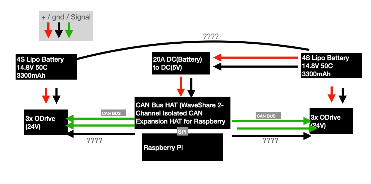
My Plan: I want to use an RPI with an Isolated CAN hat. That is connected to two times → 3 Outdrives (24V) and a 4s LiPo. (the RPI is powered by one of the two batteries using a DC-DC converter).
I am playing to run at a high current limit (30A on all 12 Motors) so I also installed some fans.
Some things I learned from other forum posts that I will implement:
I will also be using ferrite rings on the motor leads. I will use shielded cables for the encoders and thick cables for power delivery that will be kept as short as possible. The power delivery will also be arranged in a BUS pattern to have shorter runs.
In addition, I will use XT90S connectors to help with Inductance issues.
I am also using a 4s battery to keep well below the 24V current limit.
To clarify: The CAN bus is planned as one continuous BUS connecting all 6 ODrives, the picture could suggest otherwise.
My question:
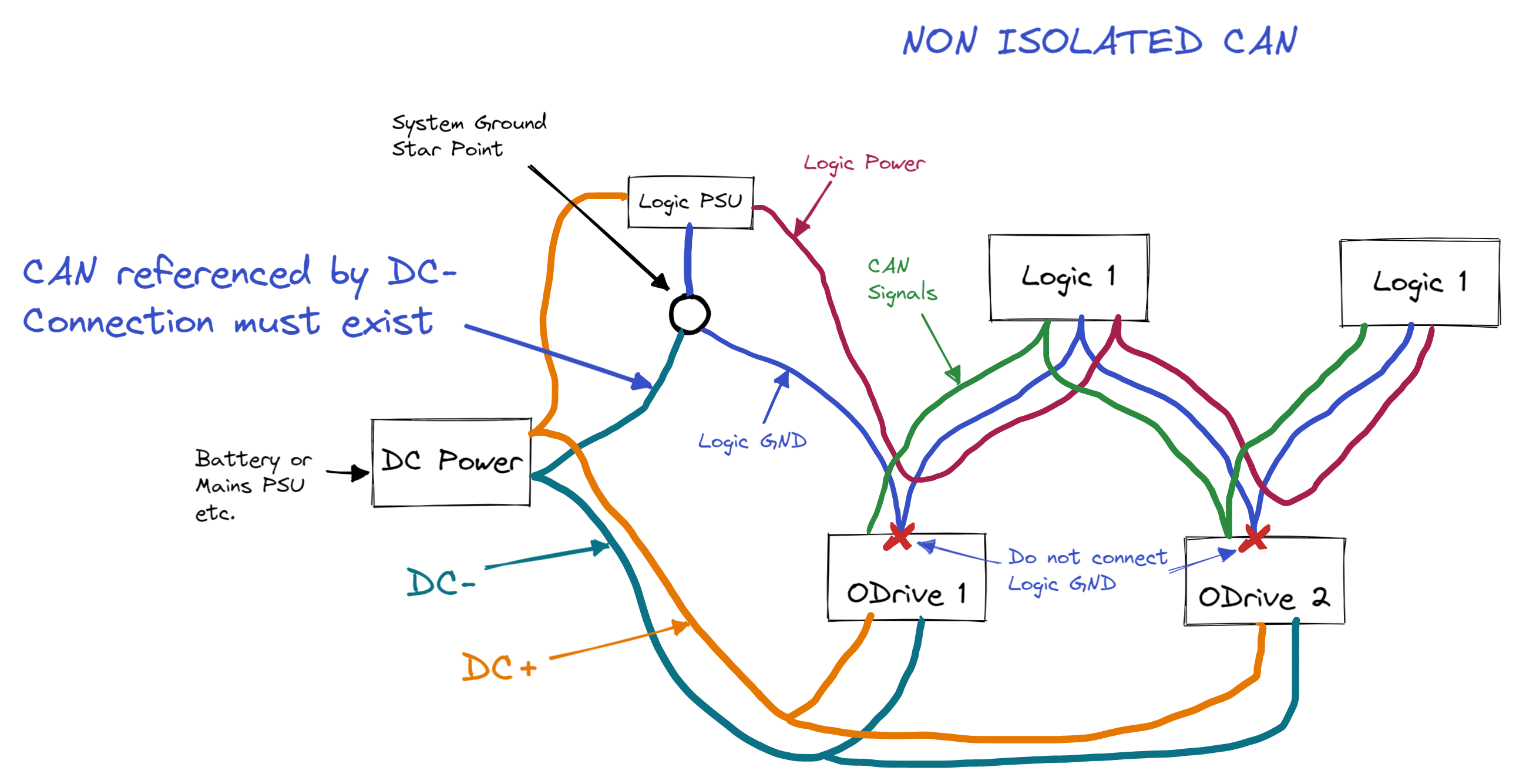
- I read conflicting information regarding the ground connection when using Isolated CAN do I need it or not?
- Using two batteries, should I connect the two grounds so that there is no voltage difference between them?
- Anything else I missed regarding ground loops or other dangers?
Thank you for the help!