I’ve seen a few robotic projects get into difficulties when the current draw from the motors caused fluctuation in the battery output. This isolator is intended to isolate the high current demands from the more sensitive components.
My concern is that an optoisolator is a linear one-way communication, but Rx/Tx is two-way, would an optocoupler block the bi-directional signal?
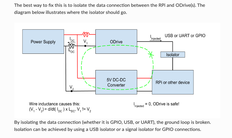
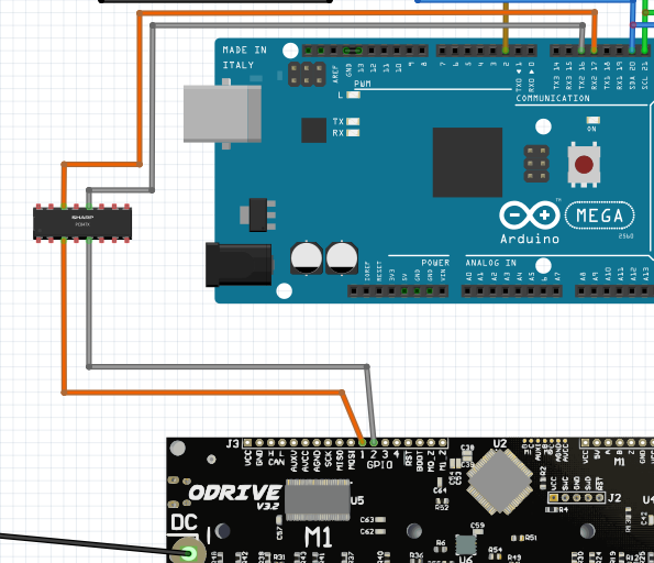
If it is oka to use, this is how I’d wire it: The diagram below is from the oDrive documentation on Ground-loops. It just shows the block-schematic arrangement, not the actual wiring connections.
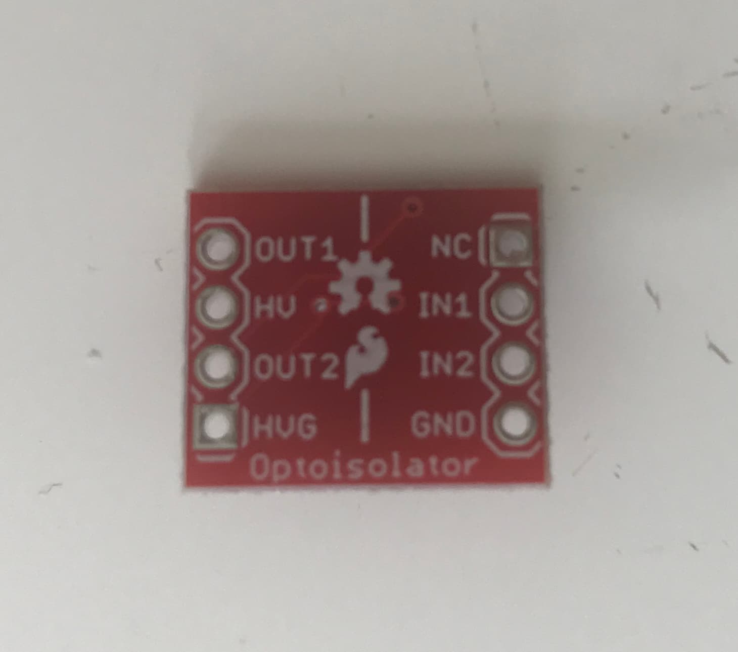
Would it be appropriate to connect the Rx and TX wires to in1, in2 and Out1, Out2, the connect the Odrive’s 5v out and ground to the HV side, and the Arduino’s 5v out to NC (and Gnd to the Arduino’s Gnd)?
UART (Rx/Tx) is not bidirectional. Tx only outputs data. Rx only receives.
Device 1 Device 2
Tx =====> Rx
Rx <===== Tx
No data ever flows from Rx to Tx. This allows you to use a simple isolator. Connect the Tx output to the one input of the isolator. Connect the corresponding output of said isolator to the Rx input of the second device. Do the same in reverse for the second datapath.
You also have to take care where the isolators isolated sides get powered from. Do not connect the power connectors.
I would advise you not to use this optocoupler as its rated speed is very low. (Only 9.6 KBit/s). The The isolator in my design is rated for up to 25MBit/s.
I don’t sell any assembled boards but it is very easy to build it yourself. Any reputable PCB manufacturer can produce the circuit board. And then its only the isolator ICs and some capacitors to solder on.
Just to clarify what I mean by bi-directional. The Arduino sends TX signal to the oDrive’s RX, but the oDrive also sends response back from its TX to the Arduino’s RX. A one-channel opto-isolator would only carry one of these TX to RX signals because it only has one Led and receiver.
Your suggestion of using digital, would allow both TX/RX routes to transmit receive.