We have an ODrive S1 with a D5065-270KV motor and an AMT21xB-V-OD RS485 rotary encoder. The motor is driving a linear stage through a ballscrew. The linear stage’s position is then measured with a linear incremental encoder. We configure the ODrive with the commutation encoder being the rotary encoder and the load encoder being the incremental encoder. When we go into Torque mode, the motor goes into spinout error very quickly.
The strange thing is, when we use the RS485 encoder as the load encoder, torque mode works perfectly, but when we switch to the incremental encoder as the load encoder, suddenly we get very unstable behaviour (stage is shaking) and we get spinout.
It is also useful that I communicate our settings for the following parameters:
axis0.controller.config.use_commutation_vel = False
axis0.controller.config.use_load_encoder_for_commutation_vel = False
With these parameters, how can the selection of the load encoder have an influence on Torque mode? I thought that only the commutation encoder was used to do the commutation, so I wouldn’t expect an influence.
In the end, we want to go into position control with the incremental encoder, off course, but we cannot even start the tuning when the torque mode is not even working properly.
Update: I think I have found the issue. When setting the velocity limit too low and hitting that limit, in some way it created the unstable behaviour. Increasing the velocity limit resolved the issue.
I think when you’re moving the stage, the velocity is increasing/decreasing very fast, which leads to a corresponding change in torque, which then leads to a spinout error.
The velocity-based torque limiting is also dependent on vel_gain (since velocity limited torque mode is equivalent to torque limited velocity mode with vel_integrator_gain=0), so if the vel_gain is unstable, then the torque control will also be unstable.
The simplest thing here is to just set axis0.controller.config.enable_torque_mode_vel_limit to False. Raising the vel_limit as you did will also decrease the effect of torque limiting at lower speeds/torques, so that’s why your approach worked.
I’d note that since your commutation encoder is such high resolution (the AMT212-B-V-OD is a nice encoder), setting use_commutation_vel might be a good idea, especially if the “effective” resolution is higher than the linear encoder, given the linear encoder’s resolution and ballscrew pitch – especially if there’s any backlash in the system.
I’m tried now to set use_commutation_vel to True, and indeed it made everything more stable. I had some struggles setting the right parameters for inc_encoder0.config.cpr and axis0.controller.config.commutation_vel_scale, so I thought I’d share what I found, so others can also see it.
My encoder has a resolution of 1 µm, which means the A and B signals both have a pulse every 4 µm and this is multiplied by 4 with the quadrature encoding. My ballscrew has a pitch of 10 mm. So every revolution of the motor, there should be 10000 counts, so I have set the cpr to 10000.
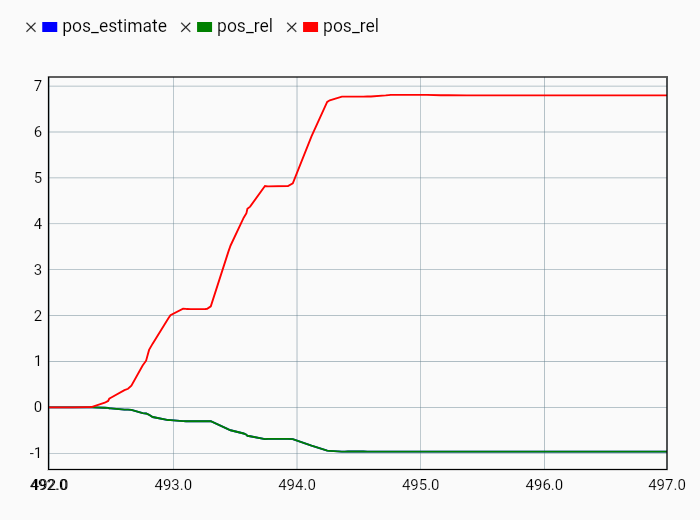
Then I checked the following parameters in the monitor while turning the ballscrew approximately 1 turn (I have set the circular range of the commutation encoder to 20, to avoid overflow:
There is a difference in scaling with a factor -7. This factor also appears in axis0.commutation_mapper.config.scale and is set to -7 after running ENCODER_OFFSET_CALIBRATION. I can only set this value to -7 and 7, as it should match the pole pairs of the motor.
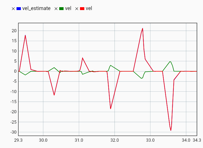
When I look at the velocity estimations, I can also see approximately that same ratio between the velocity of the control loop (vel_estimate, blue), the commutation mapper (vel, red) and the linear encoder (vel, green):
This meant that my velocity estimate is not correct and the polarity is reversed. That’s why I have set axis0.controller.config.commutation_vel_scale to -1/7 = -0.143.
If the position encoder is mounted after a gearbox with a reduction ratio N:1, this variable must be set to 1/(pole_pairs*N) (positive or negative, depending on the setup).
So I agree that a commutation vel scale of -1/7 and CPR of 10000 is correct if you want your units to be in shaft turns. If you wanted the unit to be in e.g. mm, then you could set a CPR of 1000 and a commutation vel scale of 1/(-1 * 7 * 10) = -0.0142857143