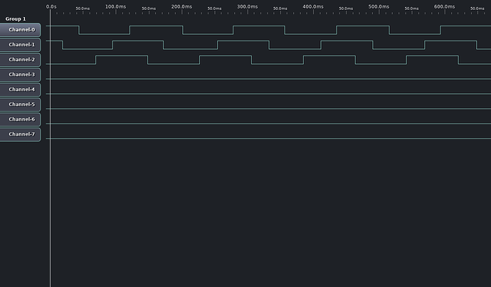
I got my odrive v3.6 24v yesterday and I’ve been trying since then to get it to drive some e-skateboard motors for a track drive robot.
The motors are generic brand you’ve never heard of ones from ebay. They are exactly like this https://aliexpress.com/item/32956554997.html just with an output for the hall effect sensors.
Problem 1:
If I try to calibrate the encoder with “odrv0.axis0.encoder.config.ignore_illegal_hall_state = False” I almost instantly get “ERROR_ILLEGAL_HALL_STATE”.
I have 47nf ceramic caps between each of the encoder inputs and ground for both m0 and m1. Maybe I need bigger caps?
Problem 2:
If I try to calibrate the encoder with “odrv0.axis0.encoder.config.ignore_illegal_hall_state = True” sometimes calibration will work and I see the motor move in one direction and then the other. Sometimes I’ll get “ERROR_CPR_OUT_OF_RANGE”.
I followed the hover board guide that says the cpr should be the number of pole pairs * 6. There are 14 magnets in these motors so 7 pole pairs (I think) so 7 * 6 is 42 and that’s what I have in “odrv0.axis0.encoder.config.cpr”. I guess whatever is causing #1 is also causing this.
Problem 3:
When I do manage to get the calibration to complete the movement of the motors is very jerky at low velocity and a lot of the time they don’t move at all or stop moving when load is applied and only start moving again if I spin the motor by hand. I’m guessing that it’s jerky because the sensor input is bad but maybe I’m missing something else.
Problem 4:
If I have axis 0 in closed loop mode but not moving and axis 1 in closed loop mode and moving axis 0 will twitch. Stopping axis 1 stops the twitching. So I think the magnets in axis 1 are affecting the hall sensors in axis 0? I thought this could be the cause of problems 1,2 and 3 but disconnecting axis 1 and moving it far away doesn’t help.
Any help would be appreciated. I only have a 2 channel scope so I can’t capture all 3 signals. I do have a 16 channel logic analyser. If the traces for that would be helpful I’ll wire it up.
Cheers,
Daniel
