Hi everyone,
I’m working on a project called Joyride, and I’d love some help, mainly around the encoder setup for a new configuration, but also general feedback on the overall design.
Project overview
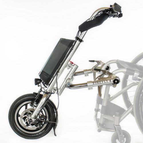
Joyride is an adaptation of a wheelchair power attachment, that is normally steered using a bicycle-style handlebar. The goal is to replace that steering input with a joystick-controlled system.
This is intended for my partner, who has a neuromuscular condition that makes it difficult to operate a traditional steering handlebar. Instead, we’re using a motorized steering system driven by joystick input, with ODrive handling the motor control.
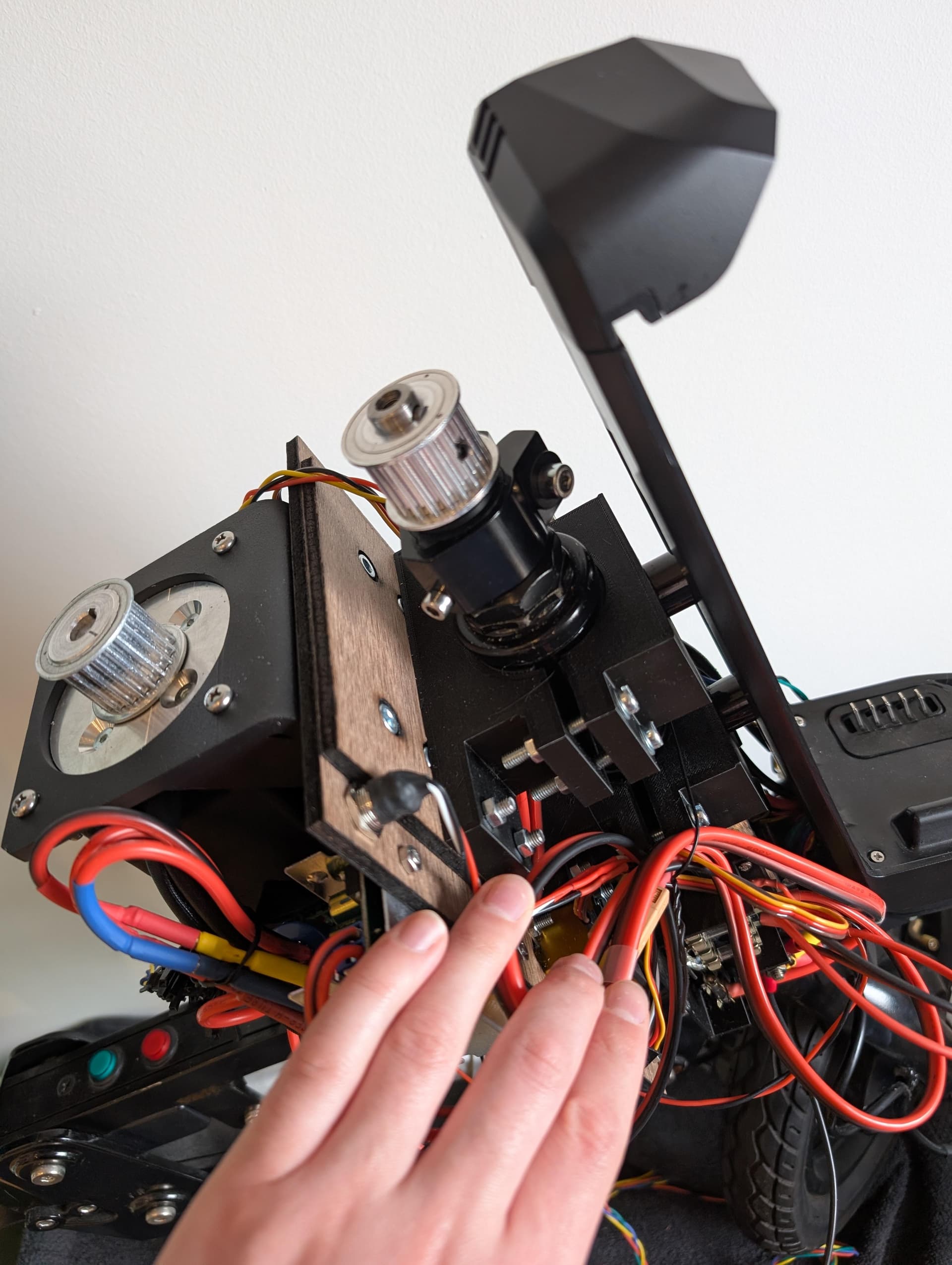
Current setup: belt drive
Our first prototype uses a belt-driven system. We mounted a laser-cut plate onto the head tube, with an ODrive D6374 motor positioned parallel to the steering shaft. The motor drives the steering through a timing belt. An ODrive S1 is mounted on the back of the motor, and we’re using its onboard encoder for both commutation and load feedback. Control is handled by an Adafruit Feather M4 CAN Express, which reads joystick input and communicates over CAN.
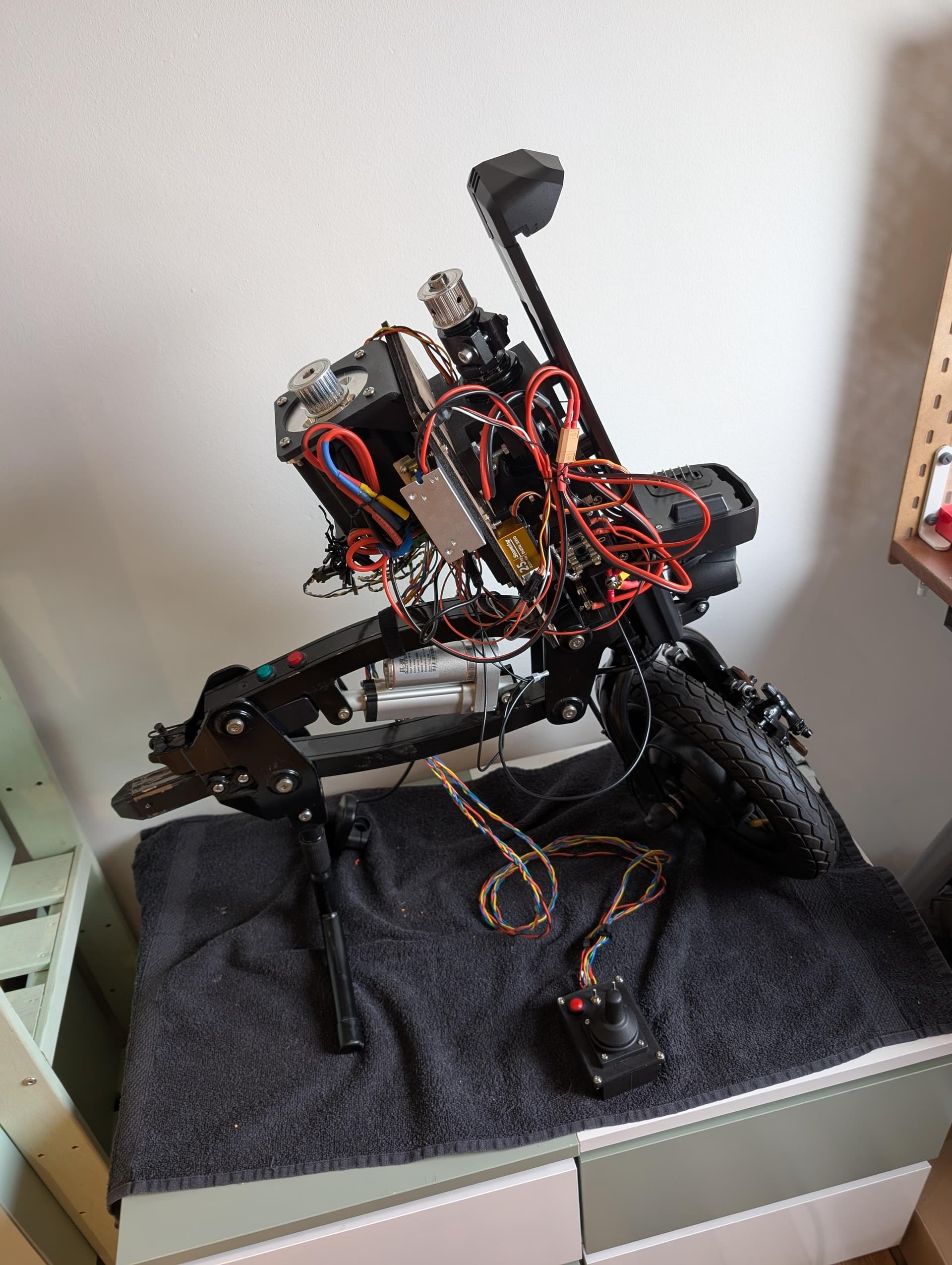
In testing, this setup gave mixed results. Without load, we were able to tune the system to behave reasonably well and follow joystick inputs. However, under real conditions the limitations became clear. The belt introduces noticeable compliance, which causes the steering shaft to miss its target positions. When I sit in the wheelchair and apply real load, the motor approaches its current limits without actually reaching the commanded position. So while the concept works, the mechanical transmission is clearly a weak point.
New setup: direct drive
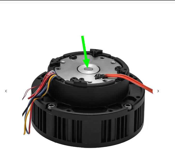
We’re now moving toward a direct-drive approach using a geared motor (Steadywin), mounted directly on top of the steering shaft.
This seems to be a much better setup: smaller form factor, higher torque, no transmission.
This change does require some redesign. Mechanically, we’ll need a custom shaft and adapter to connect the motor to the steering column, and a custom (likely 3D-printed) mount to attach the motor to the head tube. On the sensing side, we can no longer rely on a single encoder for everything, so we’re planning to separate commutation and load sensing. The current idea is to use a magnet on the motor shaft for commutation, and a ring magnet on the steering shaft for an off-axis load encoder.
Encoder questions (main ask)
This is where I’d really appreciate some guidance.
It seems that the onboard encoder of the ODrive S1 can not be used in this configuration. The required magnet distance is around 1 mm, but with the heatsink and mounting constraints we end up closer to 4 mm, which I believe is too far for reliable operation.
So as far as I understand, this means I’ll need external encoders for both commutation and load. From reading the documentation and forum posts, I get the impression that I can’t mix SPI and RS485 encoders, and that using multiple SPI encoders is also not supported. If that’s correct, it seems like I’m effectively limited to using two RS485 (OA1) encoders.
What I’m unsure about is whether that’s the best approach, and whether an OA1 encoder would work reliably in an off-axis setup with a ring magnet on the steering shaft. I’m also wondering if there’s a simpler or more standard architecture I might be overlooking here.
Other aspects (for context)
For input, we’re currently using an industrial APEM joystick in a custom 3D-printed housing. In the future, we’d like to switch to the Xbox Adaptive Joystick, since it should be much easier for my partner to use.
Braking is currently handled by two servos pulling on brake cables. This works, but it’s not ideal. We don’t have proper force control, and it doesn’t feel particularly robust. We’re considering either switching to smart servos (like Dynamixel) or adding load sensing with a PID controller.
What I’m looking for
I’d really appreciate feedback on the direct-drive approach, and especially on the encoder setup given the constraints of the ODrive S1. If anything in the mechanical design or control strategy seems off, I’d much rather catch it early.
Thanks in advance!