I want to run this motor at the rated speed of 4000RPM and I am unable to reach it. It will always stop going up at 1800 RPM (40 when I read it with the encoder). I increased the limits of current and velocity a lot and it doesn’t change anything. My max current is set at 8A but only 0.7A is being sent from the power supply (30A max). I use this odrv0.axis0.encoder.vel_estimate and the motor starts making noise at 30 but doesn’t shake. It goes to 43 and then stabilize at 40.
Any idea or recommandation I should try to fix this problem?
Thank you
I have no load attached to it and I measure 1800 rpm with a tachometer but the encoder reads 40. My power supply is set to 24V but I used 12V for resistance_calibration_max_voltage because I would get 2 errors every single time if I try to do 24V (modulation magnitude and inductance out of range). Not sure if it caused by this
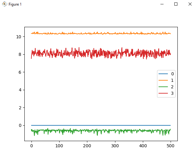
0 is Id setpoint
1 is Iq setpoint
2 is v integral d
3 is v integral q
I did a mistake when I set up my pole pairs so I have 4 pole pairs so I read a velocity of 76 and it can’t go higher. My tachometer still reads 1800rpm. I suspect my power supply to not show the proper values for current because it shows 0.9A when I reach the maximum speed of 1800rpm
feedforward terms disabled in ODrive config (they are disabled by default)
motor parameters from datasheet
we can do the following calculations:
v_{backemf} = 2/3 * 0.036 * 40*2*pi = 6.0318578948924015 V
I \cdot R = 10.4 * 0.28/2 = 1.456 V
v_q = v_{backemf} + I \cdot R = 7.487857894892402 V
v_d = I \cdot \omega \cdot L = 10.4 * 40*2*pi * 0.54e-3/2 = 0.7057273737024111 V
These numbers would match your plot if you factor in a bit of additional resistance in the motor wires.
(Note that under the stated assumptions, the P terms of the PI current controller would be 0 and the integral terms describe the actual output voltage)
However we need some additional info to verify this: