I have an iPower GM5208-12 motor connected to an ODrive S1, with an AS5048A encoder. There is a plastic disk connected to the motor that I want to spin at a constant velocity, so practically no load on the motor.
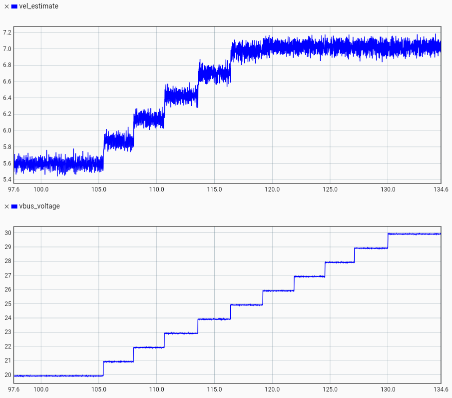
The problem I encounter is that the ODrive seems to actively limit the velocity for a reason I do not understand. I expect it to be able to spin at k_v * v_dc * 0.78. The motor is rated at 24 rpm/V, so with 24 V it should reach 450 rpm, and at 30 V up to 560 rpm. However, the velocity saturates at around 420 rpm at 25 V and doesn’t increase further with increasing supply voltage. Setting the target velocity to 15 rps and slowly increasing the voltage from 20 V to 30 V yields the following behavior:
On an oscilloscope connected between two motor phases at the ODrive terminals I can observe that at 25 V, the motor voltage does indeed reach the maximum 78 % duty cycle during the sine wave peaks. However, at 30 V, the duty cycle only goes up to around 66 %. The effective voltage is 25 V * 78 % = 19.5 V and 30 V * 66 % = 19.8 V, so this matches the observed behavior.
The ODrive is configured with the following values (I believe these are all the relevant parameters):
# Power supply
print('Configuring power supply')
odrv0.config.dc_bus_overvoltage_trip_level = 31
odrv0.config.dc_bus_undervoltage_trip_level = 10.5
odrv0.config.dc_max_positive_current = 2
odrv0.config.dc_max_negative_current = -0.01
odrv0.config.brake_resistor0.resistance = 2
odrv0.config.brake_resistor0.enable = True
odrv0.clear_errors()

# Motor parameters
print('Configuring motor parameters')
odrv0.axis0.config.motor.motor_type = MotorType.PMSM_VOLTAGE_CONTROL # For a gimbal motor with high phase resistance
odrv0.axis0.config.motor.pole_pairs = 7
odrv0.axis0.config.motor.phase_resistance = 7.6
odrv0.axis0.config.motor.phase_resistance_valid = True
motor_kv = 24 # rpm/V
odrv0.axis0.config.motor.torque_constant = 8.27 / motor_kv
odrv0.axis0.config.motor.current_soft_max = 1.5
odrv0.axis0.config.motor.current_hard_max = 3
odrv0.axis0.config.motor.calibration_current = 0.5
odrv0.axis0.config.motor.resistance_calib_max_voltage = 4
odrv0.axis0.config.calibration_lockin.current = 0.5
# run_state(odrv0.axis0, AxisState.MOTOR_CALIBRATION) # apparently not necessary for MotorType.PMSM_VOLTAGE_CONTROL
odrv0.axis0.motor.motor_thermistor.config.enabled = False
#odrv0.save_configuration()

# Control mode
print('Configuring control mode')
odrv0.axis0.controller.config.control_mode = ControlMode.VELOCITY_CONTROL
odrv0.axis0.controller.config.input_mode = InputMode.VEL_RAMP
odrv0.axis0.controller.config.vel_limit = 15
odrv0.axis0.controller.config.vel_limit_tolerance = 1.3333333333333333
odrv0.axis0.config.torque_soft_min = -math.inf
odrv0.axis0.config.torque_soft_max = math.inf
odrv0.axis0.trap_traj.config.accel_limit = 10
odrv0.axis0.controller.config.vel_ramp_rate = 10
Does anyone have an idea if there are further configuration parameters or hardware limitations that can limit motor velocity?

