Noise and Tuning Issues

I’m not making much forward progress, sad to say.

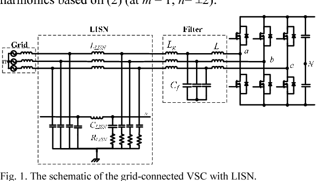
Setup is a 3.6 board, 48V with the latest release firmware. ODrive 5065 motor with CUI encoder. At first power-up I had a very bad time getting the USB to work. There was clearly a lot of noise getting into the cable. With the supplied USB cable, it would not stay connected and was receiving a lot of garbage when the motor was getting power (unexpected ACKs, random stuff). I eventually found one cable that seemed to work, and isolating the drive ground from the PC ground helped (so no ground to the drive except through the USB cable).

After the USB was working, I thought there was a lot of audible noise from the motor, sort of a mid-frequency hissing or sizzling sound. Persevered anyway. I noticed after a while that the index search was finding 7 “indices”. Suspicious, as it’s a 14 pole motor. The scope showed the encoder signal was very noisy. I looked at some other inputs. The A and B signals didn’t look too bad, but the 3.3V signal was terribly noisy.
3v3File0

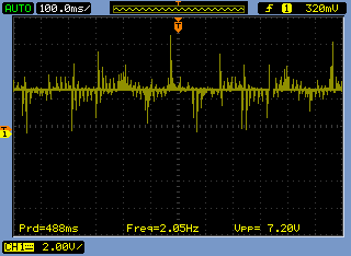
This is with the motor in position mode, not moving. The 48V power in was clean with about 80mV of ripple.

Obviously, this isn’t good. Trying to track down the problem, I eventually ended up with only the PSU, drive, brake resistor and motor connected, in sensorless mode, with motor on at 0 RPM, no encoder cable connected, no USB connected, with only the PSU case grounded. Still the same. Grounding the motor case, drive, negative power input in any combination was no help. Shielding the motor leads with metal conduit also did not help and actually made the motor audibly noisier if the conduit was connected to the motor frame.

I did find that a 47nF capacitor on the encoder input eliminated the fake indices, so I proceeded to try and tune the drive to see what happened. I had a horrible time following the instructions. I could get the velocity gain set to cause no vibration (but still audible noise from the motor). I was not able to get the position gain set satisfactorily. Using the odrivetool live plotter, I could adjust the position gain to have no overshoot on a move of (say) 0.5 revolution, but the overshoot would be enormous on a larger move of (say) 2 revolutions. Reducing the gain then made it impossible to complete the move at the lower end. Sometimes the motor would not move at all. Increasing the velocity integrator gain would pull in the position, but usually would cause oscillation. As for the velocity integrator gain, The instructions are no help as I found no way to consistently measure the position settling time.

As my application initially is going to operate in velocity mode, I thought I would try to get that working and forget position for the moment. I set the integrator gain to 0 and adjusted the velocity gain to eliminate vibration - it was 0.2 whatevers, which is close to the default. I then ran the motor at various speeds, noticing that as the speed was reduced the movement became very jerky and there was very little torque. I increased the integrator gain until the jerkiness went away and the torque increased, then reduced speed and adjusted some more, until I got smooth rotation and good torque at 0.2 RPS. I believe the integrator gain was around 15 or so. However, the higher speed (10 RPS or more) had become noisy, sounding sort of like a bad muffler, or worn gears.

Back to the scope. The encoder A and B were pretty clean, but there was clearly a lot of movement, and this was also evident on the odrivetool scope. This is a screen shot of the drive holding position:

Figure_2

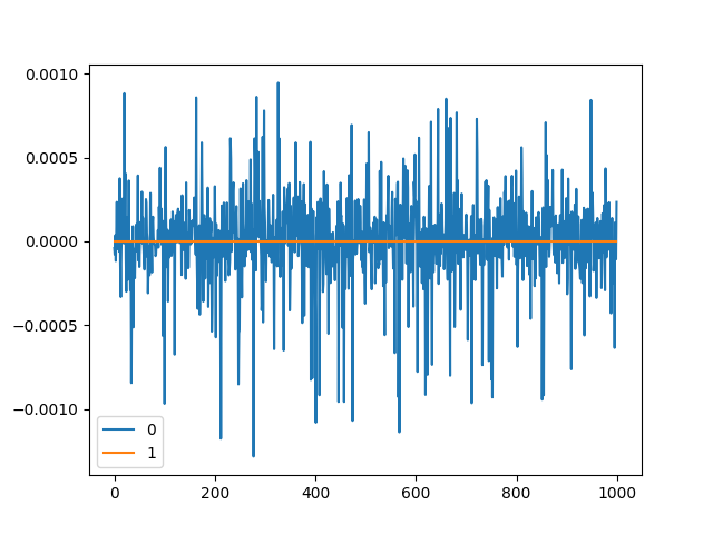
The p-p range is about 16 encoder counts. I believe this is the sizzling sound, as there is no detectable low frequency vibration.

Here is a scope trace of the one of the ground connector pins, the probe ground being connected to the incoming power negative terminal, and the scope itself not grounded. The encoder was connected but not the USB. The trace on all of the various connectors’ grounds was the same.

gnd

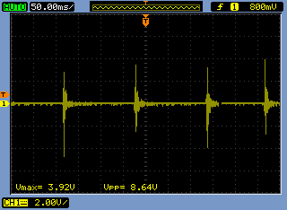
I think this is the problem, or at least the major one, but I have no reference. I noticed an earlier topic about a grounding problem on an earlier board rev - could this be a similar thing? The only other things I would suspect would be motor insulation breakdown (but the motor fame is not grounded), or a power supply issue. I did try adding bypass and large extra smoothing caps and chokes on the PSU, with no discernable difference, so I don’t think that’s it. Next I shall probably see if I can find any visible issues with the PCB, but any suggestions are welcome.

1 Like

Can you post a photo of your setup?
I’ve often seen this issue, and it can be reduced significantly by twisting motor & supply wires, and keeping lengths to a minimum.
I’d also ground the motor chassis.
If you happen to be in possession of a 3-phase common-mode choke, you could put that on the motor output. :stuck_out_tongue:

Hi, thanks for the reply. I could post a picture, but it’s only a bench lash-up before I commit to a real project, so I don’t think it would help.

Power and motor wires are twisted, and I have tried shielding and grounding almost everything, with little observable change. The wires are about as short as I can live with.

A choke seemed like a lot of work… However, I tried it and I’m happy to report that it does indeed help. Should have been less lazy, and thank you for pushing me. The ground noise is reduced by about 75% (if you look at the scope trace with the Vpp = 8.64V measurement, that measurement is now down around 2V). The live plotter trace is also showing much more stability, with a jitter of only 1 or 2 counts.

For anyone interested, the choke was very simply made by winding three coils on a toroidal core. The toroid was about 1" OD (25mm for the Imperially-challenged) and came (I think) from a defunct switching power supply AC input filter. No idea what the magnetic properties of the toroid are. Originally, there were (fortuitously) three windings of 20AWG insulated wire already on the toroid. I dropped it in the motor lines, and saw it worked, so I stripped off the windings and put on new windings. Each winding was three turns of 12AWG (roughly 2mm diameter) enameled copper wire. 12AWG copper is thick and not very bendy and the nine turns barely fit the ID of the toroid. Also, it work-hardens! I think the original windings would probably have been just fine. The inductance of each new winding was about 0.04mH.

This worked well enough so I have not attempted to optimize it. I haven’t looked into the math to figure out what the ideal choke inductance would be, if there is such an ideal, except I notice most of the off-the-shelf chokes I glanced at have very much higher inductance, which could upset the ODrive firmware.

Another reason I was not hurrying to try a choke was that I had already tried the exact same setup with a clone single-axis ODrive, and the ground noise was significantly less, so I had talked myself out of a problem with the motor, wiring, PSU or encoder. And it may still be that there is an issue with the ODrive ground buss design that pops up occasionally. However, I’m happy to have gotten past this latest hurdle…

1 Like

We also sell a recommended choke on the website. I’m sure you know that the more turns you can get through it, the better. ODrive is pretty happy with higher inductance, means the current controller bandwidth requirement is reduced

I looked at the shop, and was about to say “That’s not a common-mode choke! That’s just a ferrite ring!” But then when I thought about it, I suppose they are the same thing… :slight_smile: :+1:
Although there are a lot more turns on this one. :stuck_out_tongue:

I did not see the choke in the shop. I was actually surprised that 3 turns did the job, but from the info in the shop, it seems 1 turn might often be enough in may cases. Good to know, as it is much easier just to loop the motor wires through a toroid, if that’s an option and if they fit.

I saw a similar choke on Digikey for $15 and thought that was pricey… The inductance is 8 times what I measured, so is likely to be overkill. The diameter is 3 times bigger also. Plus the voltage rating is way higher than needed. Notice too that it uses 3 wires in parallel for each winding, which is a good trick if you don’t have any thick wire.

Wetmelon, are you saying adding inductance would be a good idea, even if not required? If so, why, and are you talking only about common mode inductance or more generally? There are a couple of points: if I’ve read the right stuff on the internet, a common mode choke doesn’t increase the phase inductance (“Summarizing, an ideal common mode choke looks like a simple wire for differential mode signals while it looks like an inductor for common mode signals”), so it would not affect the current rise time. I noticed this when I recalibrated the motor and saw only a small change in the measured phase inductance with the choke in circuit. This also seems to imply you can’t overdo the inductance of the choke, if it’s balanced, so you can increase it as needed with no ill effects.

Secondly, I did try a large commercial 3 phase choke I had in-hand, but it turned out to not be a common mode choke. During motor calibration, ODrive protested that the inductance was out of range. Is this just a sanity check or is there some real physical limit on the maximum inductance?

Of course 3mH is 75 times .04mH, not 8 times. Sorry!

  1. There’s a sort of sweet spot for phase inductance with ODrive, somewhere in the ~ e-5 Henries.
  2. Your explanation about common mode chokes is news to me, I thought it would increase the measured phase inductance but it makes sense that it doesn’t.

If it has 6 terminals, you can wire it either way?

Yes, it’s the same reason you can get wirewound resistors in either “standard” or “non-inductive” versions. The standard version is a straight spiral winding around a piece of ceramic, whereas the “non-inductive” version is wound forwards and then back, so the magnetic fields cancel and the resistor has extremely low inductance.
Also look up how an electrical RCD/GFI works. :slight_smile: They are literally a common-mode choke with a sense coil. If there is any net field in the core (due to a common mode current, which can be assumed to be flowing to Earth, perhaps via some poor sod who grabbed a live wire) they will detect it and cut the power.

Interesting discussion.

The choke I was referring to is an enormous 7.5KW unit. It has three separate inductors built on transformer-type iron laminations, with no coupling between them. Also has some capacitors and some overvoltage suppressors. I believe the primary purpose is to reduce the power-on surge into the AC-DC converter of the drive system, so the inductance is very high.

Ideally, the mutual inductance (M) of the CMC is the same as the winding inductances (L, L=M); the common mode signals see the sum of the winding inductance and the mutual inductance (M+L = 2L), the differential mode sees the difference (L-M = 0).

The wirewound resistor is a good analogy. But any bifilar winding arrangement won’t be completely noninductive, just much-reduced, because the inductance of each of the coils can never be exactly the same. FYI, my ODrive said the phase resistance was about 1.6E-5 H before, and about 1.7E-5 after installing the CMC. This was a quick lash-up, so that’s probably causing most of the difference.

towen, your comment about the GFCI ( as they are known in the US) is apposite. In an earlier post, I said I thought the toroid came from a PSU, but in fact I remember now it was from a GFCI. It originally had three turns of stranded insulated wires, two were a white/black pair and the other was green/yellow. That fact (rather than enameled wires) made me think of a GFCI, but I thought I might have rewound it for some other project.
The green/yellow seemed to be wound in the opposite sense so I rewound it for my first test, but left the others alone. Worked fine as it was, but I wasn’t sure about the current rating, so I rewound with 12AWG solid enameled wire. GFCIs here are rated at 15A continuous, so it probably would have been fine for my needs with the original wires.

In that case, it will increase the net inductance, shirley

The idea of a common mode choke is to be as close to zero inductance for differential mode (since the fields cancel) and high inductance for common mode. Whereas separate inductors will function as… inductors.
I agree it could function as an inrush limiter, or it could deliberately shift the phase off the peak of the AC mains for some reason… or perhaps it is simply an EMI filter, preventing high frequency noise from entering the AC network…

Actually, that reminds me of something I used when EMC testing:
Could it be a Line Impedance Stabilization Network (LISN) ?

image

A LISN is meant to simulate the impedance of an AC distribution grid, so that you can measure (in isolation) the conducted RF emissions of a device under test.

Or perhaps a more common PI filter as seen in the second block :slight_smile:

1 Like

The large choke I tried came from the AC input to the power converter of a commercial servo/spindle drive system and is an “input reactor” or a “line reactor” or an “AC reactor”. It was never going to be used for real, as it bigger than the motor and weighs 8 lbs. It’s definitely not a common mode choke. Its job is actually to increase series inductance to reduce surges and harmonics. Here is a pretty good description of these things: