Hello. I’m making a test bench for a motor. The motor will be connected to a hobbyist BLDC motor, and this one to an array of resistors, which will act as a load. Now, in order to model the motor at different loads, I need to change the value of resistors, which will change the power that they can dissipate and thus the load on the axis.
This is a pretty inefficient solution though, and i’ve thought of using an ESC to control the power dumped by the motor to the resistor array, that would be equivalent to control the amount of braking during normal operation. The question is simple, can the Odrive control the amount of power dumped during regenerative braking, like, limiting the current? I’ve tried looking for info on the regenerative braking capabilities but i have not found this specific question. Thank you very much.
Yes, you can run the absorber motor with ODrive and use velocity control, and set it to try to reach 0 speed, and set a current limit: this means it will brake at the current limit (because it is trying to slow the motor to 0 speed).
In my project, I’m using Odrive in quite a similar case and I have some questions.
I use a motor and Odrive in current control to create an adjustable load, always clockwise. So the motor is used as a brake.
I’ve plugged a 300W, 2.2 ohms braking resistor to Odrive with two cables with a length around 10cm and the gauge is 2.5mm² (AWG13~14). My PSU is a 48V 15A.
But I’ve encountered a problem :
-First, when I set the current to 2.0 A, I got ERROR_DC_BUS_OVER_VOLTAGE = 0x04. So I followed the steps from this website Odrive/Troubleshooting. I increased odrv0.config.brake_resistance until 2.5 ohms and the problem was solved.
-Then, when I increased the current to 8.0 A, I got the same problem : ERROR_DC_BUS_OVER_VOLTAGE = 0x04.
Should I increased again odrv0.config.brake_resistance or is it dangerous? Does the braking mode work in current control or should I switch to Velocity control and adjust the current limit?
I think boosting the brake resistance parameter by 10-15% over the actual value is fine, to account for some unknown small variations, cable resistance, resistance in the PCB, etc.
Beyond that, I think it may be the ripple current of the regenerated power that is reaching over the overvoltage limit. Do you have a 48V or 56V ODrive? Are you able to use a slightly lower voltage power supply?
I use the electric motor as a load, with a constant torque. So I adjust the torque load by adjusting the current_setpoint.
I’m using a 48V Odrive but I received a 56V yesterday. I can adjust the supply voltage around 48V +/- 10%. I will try to decrease it tomorrow. I will also try with the 56V Odrvie v3.6.
Moreover, I measured the electric resistance with a multimeter and got 2.4 ohm, so I added around 15% and adjust the setting and it seems to work now, thanks a lot.
But I encountered a new problem at high speed (300rpm, high speed for my project) which looks like the one in this thread : Error_brake_resistor . So I will check in this thread if they have a solution.
Currently, I’m using a bike motor 48V, 20 pairs of poles with Hall sensors, Kt=~1.62 Nm/A. So at 300rpm, the Back e.m.f. is around 51V >48V. So I wonder if Odrive is able to deal with the braking resistance when the back e.m.f. is higher than the maximum voltage?
I think this was your problem all along. The ODrive cannot control the current at all if the back-emf is higher than the bus voltage. So that may be causing all kinds of errors, the most expected one would be bus overvoltage, since the ODrive is incapable of stopping regen if the bEMF > Vdc.
I think your best bet would be to use the 56V ODrive and try to run your bike wheel at speeds where the bEMF is 50V or less. Also be careful that your power supply doesn’t get fried if the voltage creeps up to around 56V, my guess is that most 48V PSUs will be ok, but it may go into an overvoltage protection.
Thank you very much, I’ve tried Odrive 56V this morning and it works. I didn’t make my PSU explode but I didn’t try for a long time Anyway, the speed happens to be that fast only for a very short time, around 200ms. I will build a test bench to check how long can the PSU stand before going in safety mode.
In my case in sensorless mode: when I reach the current limit, the drive throws an error.
In [16]: odrv0.axis0.requested_state = AXIS_STATE_SENSORLESS_CONTROL
In [17]: odrv0.axis0.motor.config.current_lim=2.5
In [18]: odrv0.axis0.controller.input_vel=20
In [19]: dump_errors(odrv0)
axis0
axis: no error
motor: Error(s):
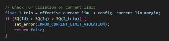
MOTOR_ERROR_CURRENT_LIMIT_VIOLATION
Procedure :
Start the motor in sensorless mode
Once spinning (no load on the shaft), set the current to a small value, set the speed to a “reasonable one”
Pinch the axis with my thumb until I get 2,5A on Iq
The drive throws an error
Is there a parameter to avoid throwing the error and just keep going with the limited current?
I still stay within the acceptable speed range for the backEMF to be readable by the drive.
I don’t think there is a specific flag, but you can adjust current_lim_margin to be really large. If you try the beta GUI, you might be able to see what’s going on with the current.
 Anyway, the speed happens to be that fast only for a very short time, around 200ms. I will build a test bench to check how long can the PSU stand before going in safety mode.