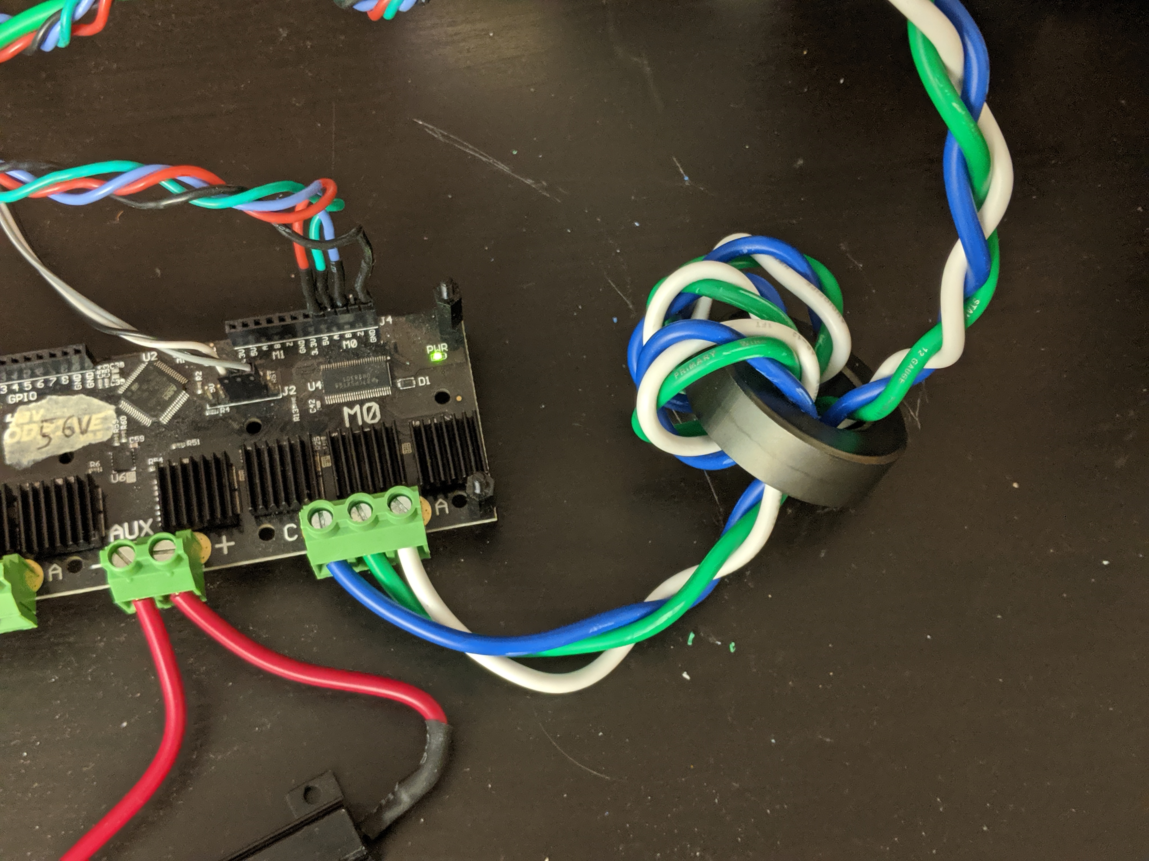
When my oDrive is set to closed loop control, it creates huge EMI at around 50 kHz. I think the majority of the noise is emitted by the three cables of the motor.
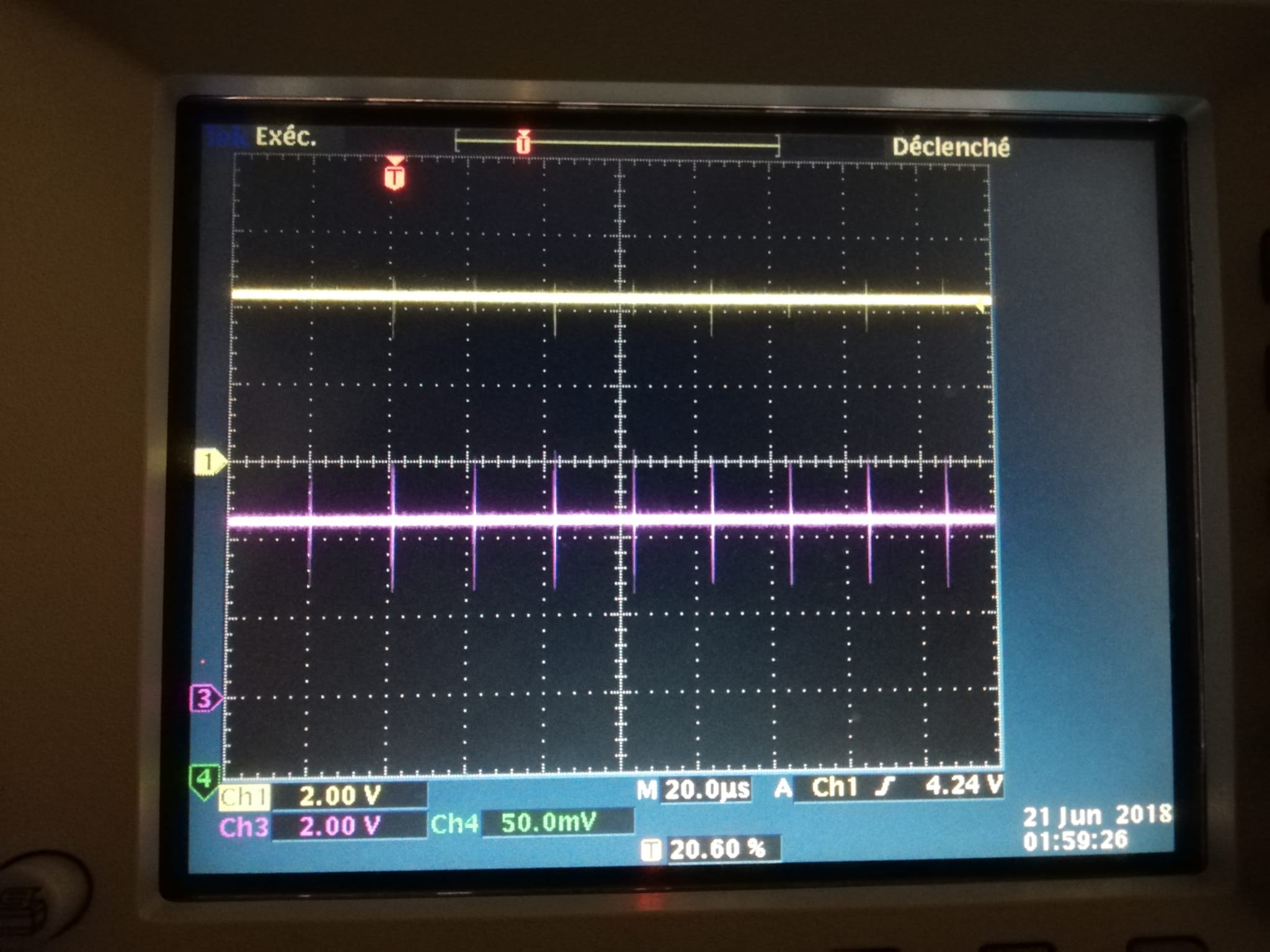
This noise is so heavy that it disrupts an i2c communication between a raspi and an arduino that are on a different circuit than the oDrive (noise is purely electromagnetic). Here are pictures of an i2c communication (yellow is SDA, purple is SCL) when idle/sending when the oDrive is on/off :
I’ve tried to shield the three cables of my motor, which helped but there is still to much noise. Do you have any idea how I could reduce it even more?
I have sometimes found that this is reduced by lowering the current control bandwidth
ie odrv0.axis0.motor.config.current_control_bandwidth=500 or less and also reduced by lowering the power supply voltage (which may or may not be an option for you)
You should also make sure that your motor wires are kept close together or twisted, and that the metal casing of your motor is grounded.
If you have a shielded cable, then connect the shield to the motor casing at the motor end, and to GND at the ODrive end. Use the GND from the brake resistor output.
Are you running from a battery or a power supply?
Do you have a long (>1m) cable to your motor?
If so, you could try adding some filtering to the output of the ODrive.
You might try some low value (~10nF or so) capacitors between each of the three motor wires in a star configuration, close to the ODrive. This might conduct away some of the noise in the MHz-GHz range, but any more capacitance could disrupt the current sensing and make things worse.
You could also pass the power and motor wires through ferrite cores
As towen suggested above, if your motor has a good way to add an electrical connection to chassis, I would connect it to ODrive’s GND. I would not use the brake output, but rather the DC- input. It is not a big difference on ODrive v3, but we will be using low-side switching of the brake on ODrive v4, so just want to make sure the advice about connecting to the break port isn’t recommended in general.
I would not advice this, capacitance on the phases increases switching losses, and adds large switching currents which can cause inductively coupled noise in addition to the capacitive noise.
This is a good solution and also what I do when I get these kinds of issues. Put the ferrite close to the ODrive side.
This makes me wanting a modular ODrive: Motion planner CPU, bus, BLDC driver near (or integrated in) the motor. It could keep EMI causing currents more locally. Isn’t that the concept of Clearpath motors?
Trinamic builds on CANopen and CANopen over EtherCAT. Maybe that could spark some ideas. No, I’m not affiliated with them, I’m just investigating if and how I could use their ICs in my project.