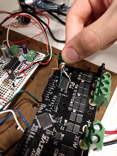
Hi,
I wrote a python script based off of “odrive_demo.py” to test the ODrive with a Harmonic Drive RSF-Mini 11B motor I’m using (Link to the page here: http://www.harmonicdrive.net/products/rotary-actuators/solid-shaft-actuators/rsf-mini). The motor seems to act appropriately to the calibration sequence to find to the encoder index but when I request a change of state to move to closed loop control and send a position command the odrive doesn’t change states.
Here is my script:
#!/usr/bin/env python3

from __future__ import print_function

import odrive
from odrive.enums import *
import time
import math

# Find a connected ODrive (this will block until you connect one)
print("finding an odrive...")
my_drive = odrive.find_any()

print("Bus voltage is " + str(my_drive.vbus_voltage) + "V")
print("Calibration current is " + str(my_drive.axis0.motor.config.calibration_current) + "A")

# Set some hardware parameters temporarily
print("setting some hardware parameters temporarily")
my_drive.config.brake_resistance = 0.5
my_drive.axis0.motor.config.pole_pairs = 4

my_drive.axis0.encoder.config.cpr = 400000

# Calibrate
print("starting calibration")
my_drive.axis0.encoder.config.use_index = True
my_drive.axis0.requested_state = AXIS_STATE_FULL_CALIBRATION_SEQUENCE

print("waiting for calibration to end...")
while my_drive.axis0.current_state != AXIS_STATE_IDLE:
    time.sleep(0.1)

# Closed loop control
print("Changing state to closed loop control")
my_drive.axis0.requested_state = AXIS_STATE_CLOSED_LOOP_CONTROL

while my_drive.axis0.current_state != AXIS_STATE_CLOSED_LOOP_CONTROL:
    print("axis errors are:")
    print(hex(my_drive.axis0.error))
    print("motor errors are:")
    print(hex(my_drive.axis0.motor.error))
    print("encoder errors are:")
    print(hex(my_drive.axis0.encoder.error))
    time.sleep(0.1)

print("current state is " + str(my_drive.axis0.current_state))

curr_pos = my_drive.axis0.encoder.pos_estimate
print("current position is " + str(curr_pos) + " ticks")

new_pos = curr_pos + 400000
print("sending to " + str(new_pos) + " ticks")
my_drive.axis0.controller.pos_setpoint = new_pos
The while loop at the end is designed to halt until the odrive to change states to closed loop control but it ends up stuck here forever. Here is the print out:
finding an odrive...
Bus voltage is 23.866186141967773V
Calibration current is 10.0A
setting some hardware parameters temporarily
starting calibration
waiting for calibration to end...
Changing state to closed loop control
axis errors are:
0x41
motor errors are:
0x11
encoder errors are:
0x0
Upon looking into the error codes I found that they correspond to these flags
axis errors are:
ERROR_MOTOR_FAILED = 0x40
ERROR_INVALID_STATE = 0x01
motor errors are:
ERROR_PHASE_RESISTANCE_OUT_OF_RANGE = 0x0001
ERROR_CONTROL_DEADLINE_MISSED = 0x0010
encoder errors are:
no errors
I’d appreciate any help. Thank you!
