So I bought the cheapest “magnetic bike trainer stand” that I could find, opened the cover and found that the magnets are easily removed, and there is a metal cup with a little fan on a nice ‘D’ shaft, clamped on with a ‘top hat’ washer.
I made a 3D printed part (PLA worked fine) to replace the fan with an adapter between the D shaft and an 8308 motor which I had handy.
I first tried with no ODrive and just a diode rectifier and various loads. A straight resistance is alright, but the torque (current) is proportional to speed (voltage), so it feels like the original cheap bike trainer: like pedalling through mud.
A lamp produces a high torque at low speeds which falls off sharply at high speeds, due to the temperature of the filament.
I’d like something that produces a constant torque (like an incline would) and maybe even some sense of inertia.
ODrive to the rescue: We can easily program a constant resistance torque, and an external script could simulate a virtual inertia.
With a few big capacitors on the input, I can even run it without a power supply.
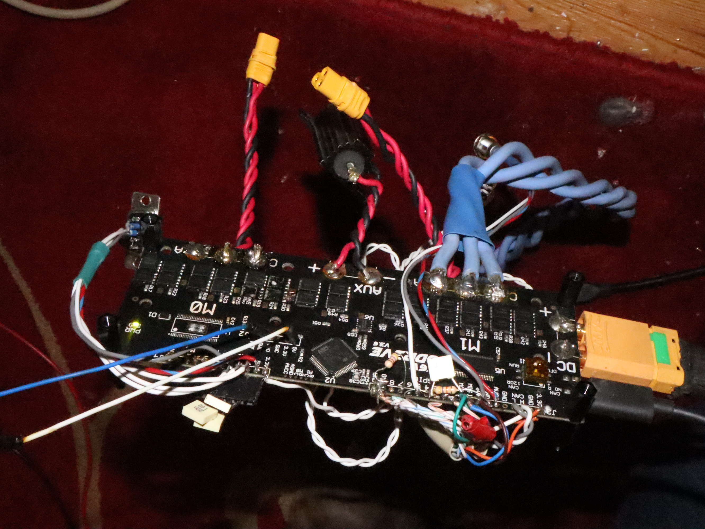
However, sadly, I have blown up my ODrive after pedalling too fast.
I had configured it to limit the voltage to 48V using the brake resistor, and that should have protected it, but apparently it didn’t. No explosions, but now the input looks like a dead short…
Oh no! ODrive should be able to protect itself - mostly - if you have dc_bus_overvoltage_ramp on, but if you pedal way too fast, it will eventually go faster than base speed perhaps?
Nope… But my guess would be one of the FETs is damaged, because the board really does appear as a dead short.
In an effort to find out what was borked, I connected it to my 15A bench power supply. I was scratching my head as I was putting 15 Watts into the board but I could not feel any component getting warm… Until I realised that 13 of those Watts were in the wires. At 15.5A (the max of my bench power supply) there is about 0.15V across the ODrive.
There is one more way to find out where the short is [was], but it involves a battery, a much higher current, and some protective goggles.
I did have this set. But I was expecting to feel a resistance torque as the speed approached this value and I did not. I can’t imagine I could have overpowered the brake resistor (2 ohms @ 48V ~= 1kW) and certainly not without feeling it, and it didn’t get warm. I also had a 12V halogen bulb connected in parallel across the brake resistor, and I didn’t see that glow at all. So something must have been wrong.
Maybe the ODrive failed to boot up properly, being powered up by the back-driving motor.
The halogen lamp should be far less resistance than the brake resistor when cold and rise in resistance as they heat, possibly to around 3 Ohm’s, will this change in resistance affect how the ODrive functions? Where it would normally expect a static resistance, yours could be going from a few milliOhms to just over 1 Ohm (considering parallel).
Also, the halogen lamp emits infra red-light until it heats up, so you may be able to see the infra-red light with a camera phone before your eyes can see it.
Wouldn’t that be active immediately on boot, though?
I suppose it takes some time to read the config from flash and start the main task - but I gave it plenty of time to get going before I slowly started pedalling faster.
I can only imagine that because the voltage would have ramped up slowly from zero, maybe the chip did not boot at all. Is the brown-out reset being used?
Then, after another press conference worth of hot air, I lifted the DRV8301 and applied power again. Of course, that chip supplies the 5V for the board, so no green light, but no more smoke either!
So, I took a little regulator board, and attached it to 5V and GND from the programming header.
It was supposed to be limiting the voltage to by ramping the brake resistor from off to completely on between 48V and 52V, but for whatever reason it didn’t.
Sweet, getting the config out really helps us nail down what the issue could have been.
When the initial fault occured, what mode were you in? velocity or torque control mode? Or simply idle and letting the Fet’s body diodes make a passive diode bridge?
Did you also have a battery or did you have nothing on the DC plug and just woke up the ODrive from the passive voltage from the bike?
Let me see in the worst case say you ran it in idle, we would actually have Ibus_sum = 0, because the regen current cannot be computed in idle. Then we have:
So in total we have brake_duty = -0.4 + 0.5 = 0.1
This may be less than is required to clamp the voltage correctly. Though when the voltage goes higher it should go up a fair bit as voltage goes up, I think it might be at 0.6 when the voltage is at 52V. On a 2 ohm brake resistor that is 800W, I’m sure you would have felt that lol.
I am not too sure what broke it in the end. As shown above running in idle and using purely the ramp without correct feed-forward term from the motor is not ideal, but yeah I still think it should have saved it. Perhaps passive diode commutation of the motor is too irregular and this causes sever bus voltage ripple which lead to incorrect bus voltage measurements?
Anyway before I go too far, it would be nice if you could confirm if there was a battery and if you were running in idle mode.
There was no battery, but I did plug 3.4 mF of capacitance into the DC Bus, which I calculated should keep the drive online for about 5 seconds (depending on the voltage it was charged to) so it wouldn’t have been repeatedly rebooting whenever I slowed down.
Wow! I’m very interesting in this project. Do you know Tacx Neo? I think you are trying to do something similar. Maybe with a BLDC as the LG washer machines has, you can get the proper resistance.
I’ve implemented my own ‘tacx neo-like’ ‘virtual freewheeling’ pedal generator (got around 85% efficiency too - using about 18x reduction coupled with a 110kv drone motor).using a vesc. Absolutely dead simple - you just need duty cycle control set to maintain your self-selected cadence given your reduction ratio, job done.
The motor spins (and unless you install a freewheel like I did - spins your legs, too) at a certain rpm, in power phases your overrun the motor and it resists up to current limits set by firmware (than it will simply ‘slip’), in dead spots you no longer overrun the motor and it offers very little resistance (or even pull your legs if you leave the system fixed gear, but I find it does not happen in practice). It feels extremely natural and pleasant, just like riding a bike at high speed. You can pedal as hard or light (provided you maintain cadence above minimum dictated by your duty cycle, and withing maximum current/torque limits) as you want.
So stuff like this makes me want to produce a video series/reality show called “Fire and Smoke Friday” where we do stuff like this testing open source hardware until the magic comes out.
I would gladly donate some time/money/boards to have root cause failure analysis like this recorded and professionally-ish produced into a weekly series


 ,
,