I was testing 1 nema23 5 amp 3phase stepper connected via step/dir with a Duet Wifi. I had issues with the velocity limit and overcurrent and repeating ramps with different settings. Once i started again a ramp, the stepper could not follow the position setpoint and stalled (the current went to max and stopped following the setpoint) - like a couple of times before. This caused a brown out (24V 25amp PSU). The duet just rebooted, but the odrive staid completely dead.
I have no access via USB and even the power LED is dark. It seems to be completely dead.
What could have caused this ?
Where to start to find the destroyed parts ?
The pcb looks still brand new - no damage visible.
Can you show us a picture of your wiring? Specifically, how is your step/dir/gnd connected to the Duet? How does the Duet get power how does the ODrive get power. Pictures of this please.
If the PWR LED doesn’t come on, then the 3.3V rail is dead. Unplug everything except power input and check if it is still dead. You can measure the voltage from 3.3V rail to GND, and from 5V rail to gnd.
I cannot show pictures because after my post i found time to start further investigations and had to disconnect everything to check the PCB closer.
Unfortunately i think i (maybe) found the mistake. When disconnecting everything, i found the GND wire connecting the Duet with the ODrive was very lose, probably it was electrically already disconnected. Looks like i have somewhen pulled it out a bit. But maybe this was after i started to disconnect everything. Could it be, that there was a small gap between the GND connectors and when the back EMF came the gap caused a spike with additional inductive problems ? But i cannot find any visible “overvoltage” signs on the metal parts.
To answer your questions
ODrive is still dead
no USB action
5 V is alive
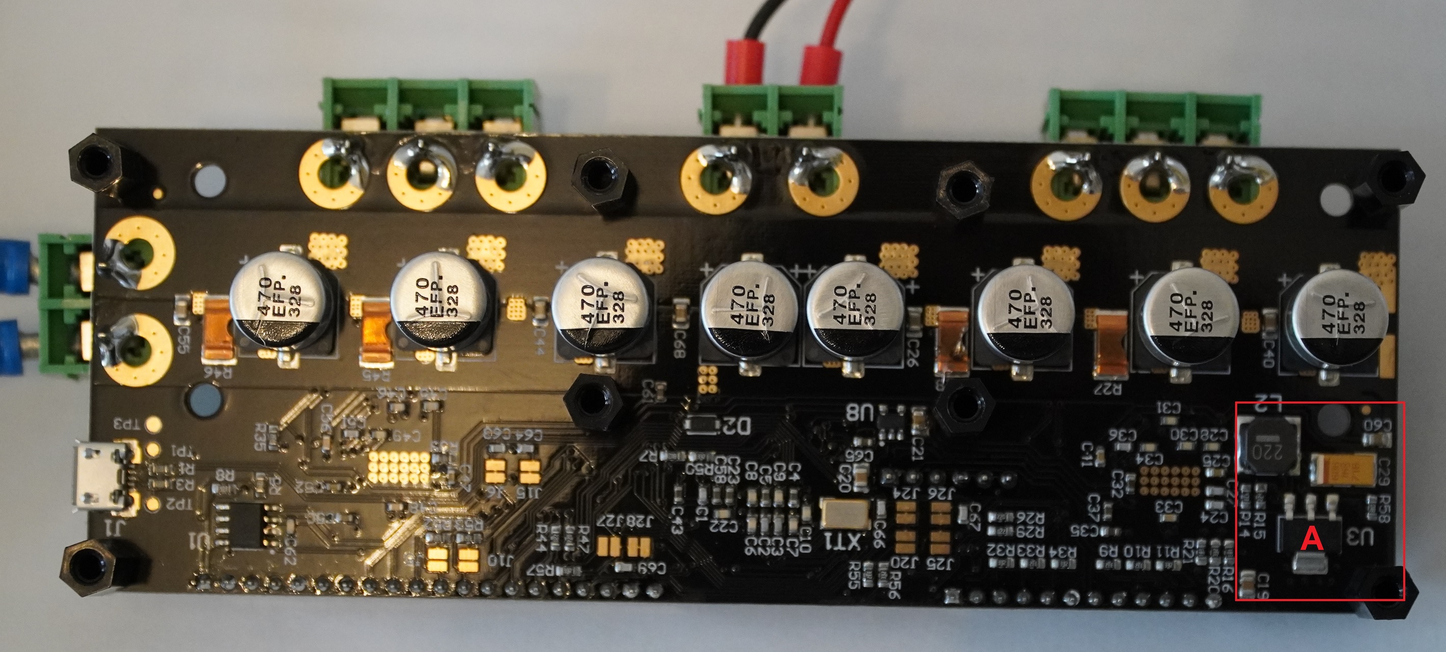
3.3 V rail is dead, 5 V also on the part marked with an A
the red marked area gets freaking hot (voltage regulator?), the other parts seems to stay cool
The setup was:
Duet Wifi as well as ODrive on same 24v 25 amp PSU
step/dir connected via Wifi Duet CONN_LCD (standard way of doing that), on ODrive side i used also the standard GPIO pins, connected with “single breadboard testing wires” (i don´t know the correct English name). GND connection between boards also per step/dir GND.
only one stepper was connect, cable length about 200mm
I would be interested if you solved the problem? If yes how?
Is it possible that you upload a wiring diagramm (odirve --> controllboard), because I ordered almost the same system and I do not want to destroy it.
It’s hard to know what exactly happened, but I would suggest to be very careful with your GND connections in general.
The 3.3V regulator U3 (device you marked A) is likely damaged. The part is this one. You could try replacing it yourself.
The solution was to order a new odrive and spare parts. Unfortunately, i ordered too quickly and again the 24V version instead of the 56V. I will make an additional post why that was wrong.
The wiring is exactly according to the odrive and Duet standard.
I did only make one change. Now i only connect the odrive and Duet GND per PSU, not also per step pins.
By connecting GND per PSU and step/dir, i created a GND loop, which is an antenna. In principle, any current flow inside the loop should cause a current int the GND loop. The PSU wires have been far away from the step/dir wires, so the covered area of the loop was big. I cannot remember but i guess the motor wires have been inside the loop. I don´t say this was the reason, but i think it was not smart to create this loop.