I recently received my first Odrive v3.6 and finally got to powering it on.
However I didn’t get too far as the motor won’t calibrate and I’m getting incorrect voltage feedback from the board. So far I’ve done the following:
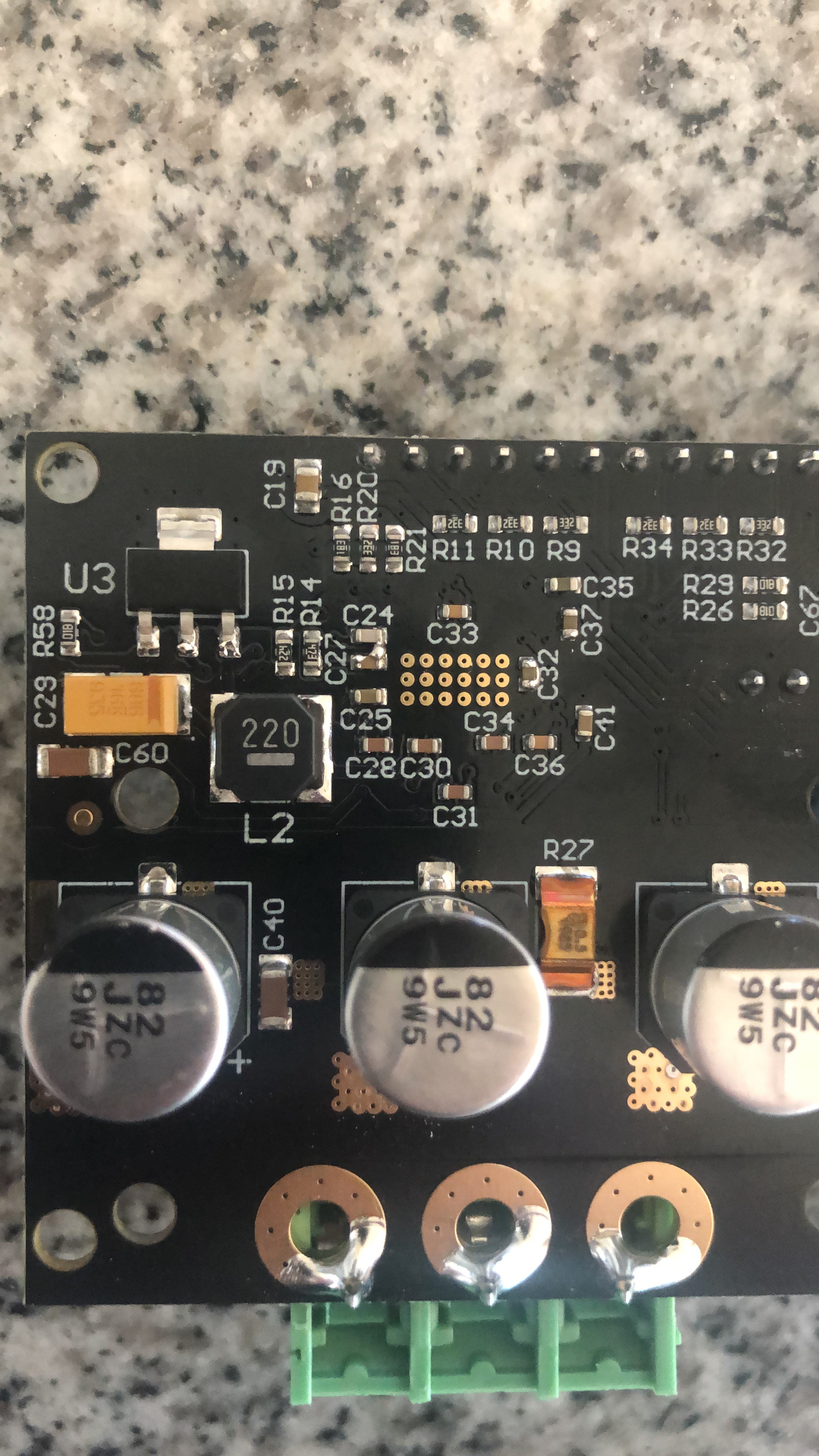
Wired up Odrive motor, cui encoder, 24 volt power supply @15 amps, and brake resistor
Ran Odrive tool and ran vbus voltage command which returned a value of 12.0 volts (checked pads with meter which confirmed pads were receiving 24 volts from the supply)
Configured motor anyways, saved / restarted, and tried to run calibration which didn’t work. Not even a beep
Ran the dump errors command but everything returned ok
Deleted config then switched to a 12 volt battery supply
This time vbus voltage matched my meter
Setup and saved config
Ran motor calibration and again no beep / motor wouldn’t turn
Ran vbus command and it returned 12.0 as it did previously
Dumped errors but everything was showing as working / no errors
Reflashed the board and repeated all of the above
I was never able to get vbus to show a value other than 12.0 volts again. Board doesn’t seem to have any visual defects.
Is the board defective or where do I go from here if I’m not even getting any errors to go off of?
Can you provide more info on your power sources? I use a 32 volt power supply and usually only read 30ish volts and when using lipos get accurate voltage readings so I can maybe be able to help.
AC to DC 24 volts at 15 amps (works fine on some brushed controllers I have)
12 volt 80 amp DC battery
7s Turnigy Lipo at 5ah
Only for a brief moment did the 12 volt 80 amp battery give me a correct reading, but calibration didn’t work anyways. Not even a beep.
I’m assuming the board has a defect. It’s pretty hot to the touch, although I can’t visually see any issues with it. As someone that’s gone through quite a few quad copter boards / escs, I can almost always visually tell where the issue is so I’m perplexed by this.
And just as I say that I scan the board again and see this… I’m no EE but I’m assuming that’s not ideal? Looks like two chip capacitors are bridged (c27 and c24). Could this lead to the issues I’m experiencing?
Well, I got anxious while waiting for the Odrive community to chime in except Joe of course (thanks Joe!).
I checked the schematic and noticed there would probably be quite a bit of noise going back to ground with those caps bridged. So I checked for shorts and found little resistance on either side of the caps.
Got my handy dandy magnified glass (closest thing I have to a microscope like the pros in the labs use when they need a quick fix) soldering iron, copper mesh and went to town. Ended up having to just pull one of the caps off the board because the mesh was taking too long to pull the solder up (it was a huge glob for that size of a cap).
Getting the cap back on wasn’t easy. Definitely the most difficult thing I’ve ever soldered. But somehow I got it to stick haha.
Long story short… turned the board on test voltage, no magic smoke, hooked the motor back up with full power and boom calibration works. None of the work was quality warranty stuff so who knows how long that cap will stick but at least I have a working board now.
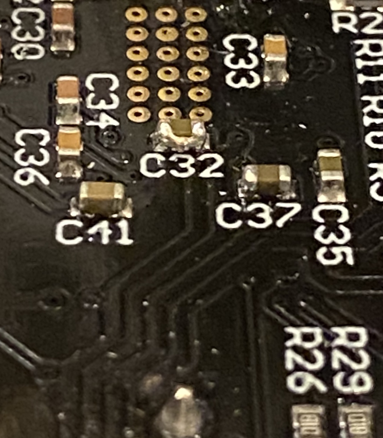
Oh and while I was in there I noticed cap C32 that leads to M1 Texas Instruments board if I remember right was bridged to itself (so picture below of the before). Figured that wasn’t ideal either but had little patience left so I got riskier and pulled out the solder sucker to take care of that one.