Doh, I am in the midst of printing the original open torque actuator and yeah $70 for a used cross roller bearing was the best I could find. The Alibaba link in the BOM seems to be dead, and really I have never had success ordering from an alibaba supplier anyways. They claim they will do single quantities but then my orders always get “canceled”. There doesn’t appear to be any suppliers on aliexpress for the RA8008 either. They have the smaller RA7008 though, but those are more than the motor.
I thought the cross roller bearing was used because of the axial forces that the sharp helical gears cause. Was that a consideration in your design?
I think the cross roller bearing is just a way to take on lot’s of axial and radial forces in a very small and lightweight form factor. This is good if you want to use it in a robot arm, but for me it has no big advantage since I will mount it on a table.
This design is a bit heavier and longer but can also take on high forces. I actually think that if you would put a heavy torque on this motor, you would probably end up destroying the 3D printed parts before actually damaging the bearings…
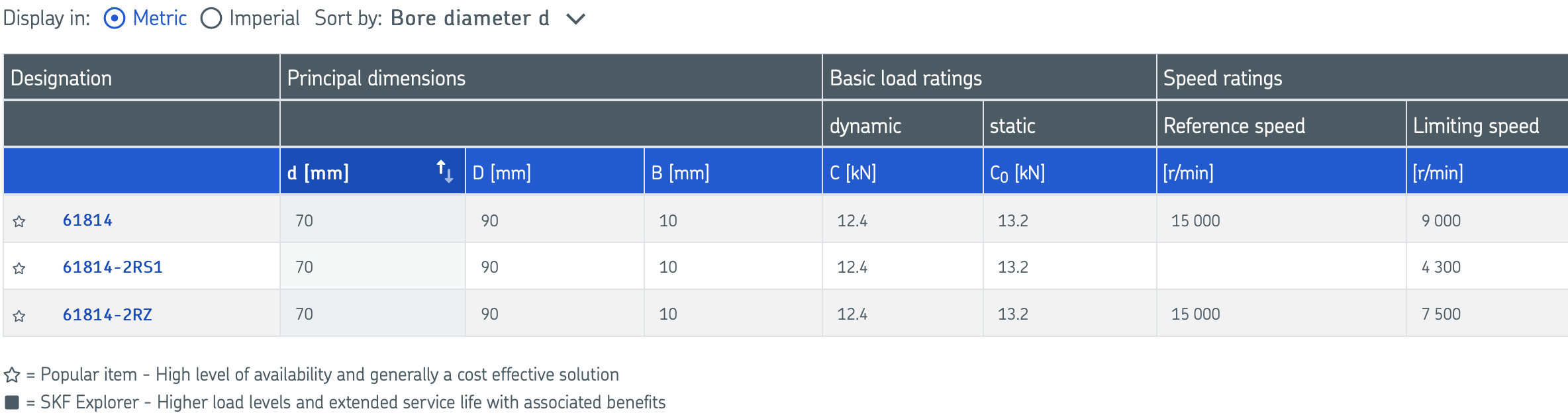
I didn’t perform any calculations, but I’m sure the forces of the helical gears are small compared to what such a bearing can take. See for example the load ratings in this table from SKF
Very nice design & write-up! I have nearly finished printing one of my own.
I did the output planet-carrier part in polycarbonate (black) but the bottom face has warped slightly. Probably still usable.
Also, I did the polanet gears in TPU. They are tough but slightly rubbery/compliant, but also a bit of a tight fit. No backlash whatsoever and very quiet, but might have to scale them down slightly for the friction. I removed the seals from the inside-facing sides of the bearings to try to reduce friction there.
In total I’d guess it’s about 0.2Nm of friction back-driving the gearbox - not measured properly yet, but I can back-drive it if I press the palm of my hand against the output side. Will be interesting to see if it’s still back-drivable with a motor attached.
A couple of things I have noticed so far:
The back-side of the planet carrier doesn’t seem to mate with the front-side, but that may be because my front side is warped slightly.
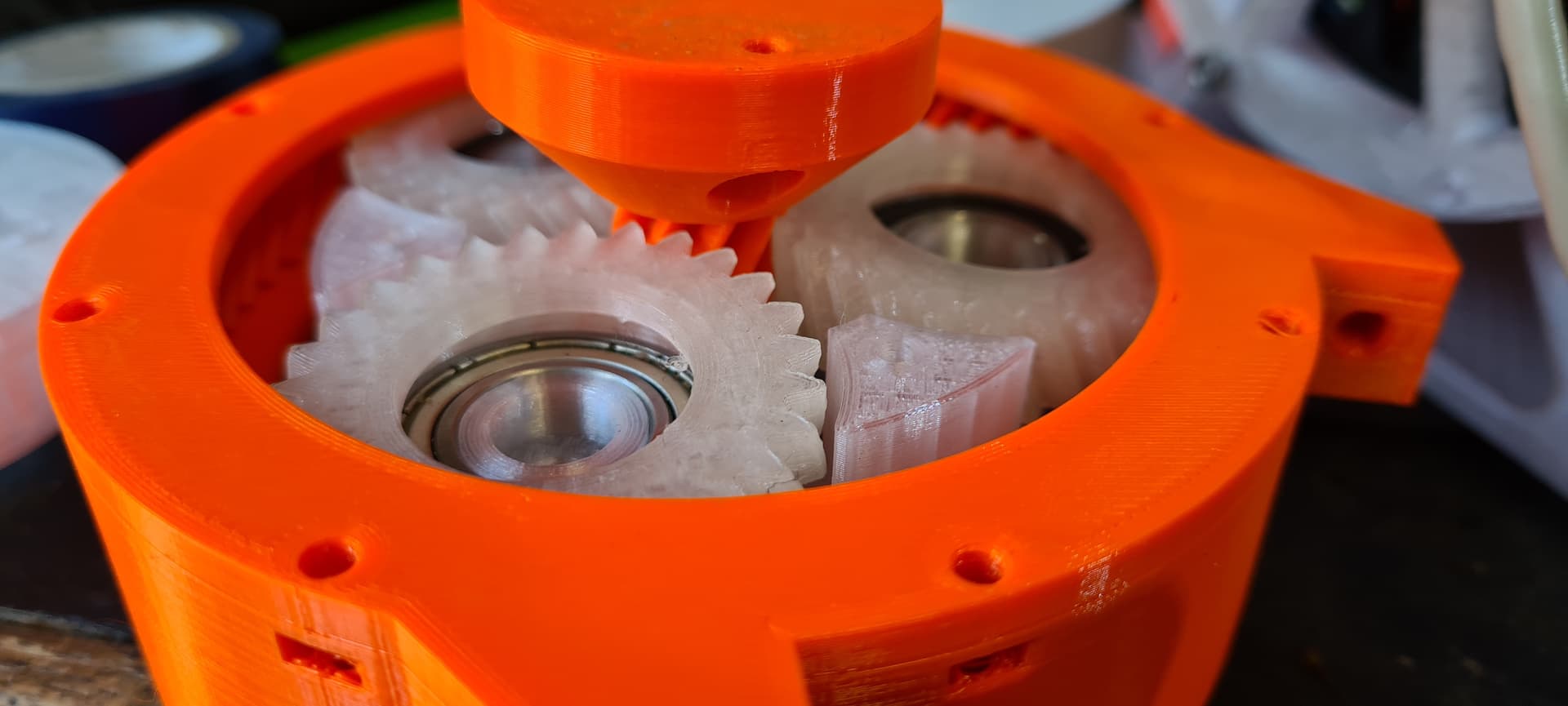
The sun gear spline could be longer. If it is flush with the gears on the output side and the gears are pushed all the way towards the motor, then there is hardly any clearance above the back-side of the planet carrier. That might work for your motor which has a raised section there, but mine is flat on top so it might foul against the planet carrier.
As for the feedback, normally the pieces should mate nicely, so I think indeed it’s because your part was warped. I think I understand your second point, let me know if it does not work well, I can revise the deign if needed.
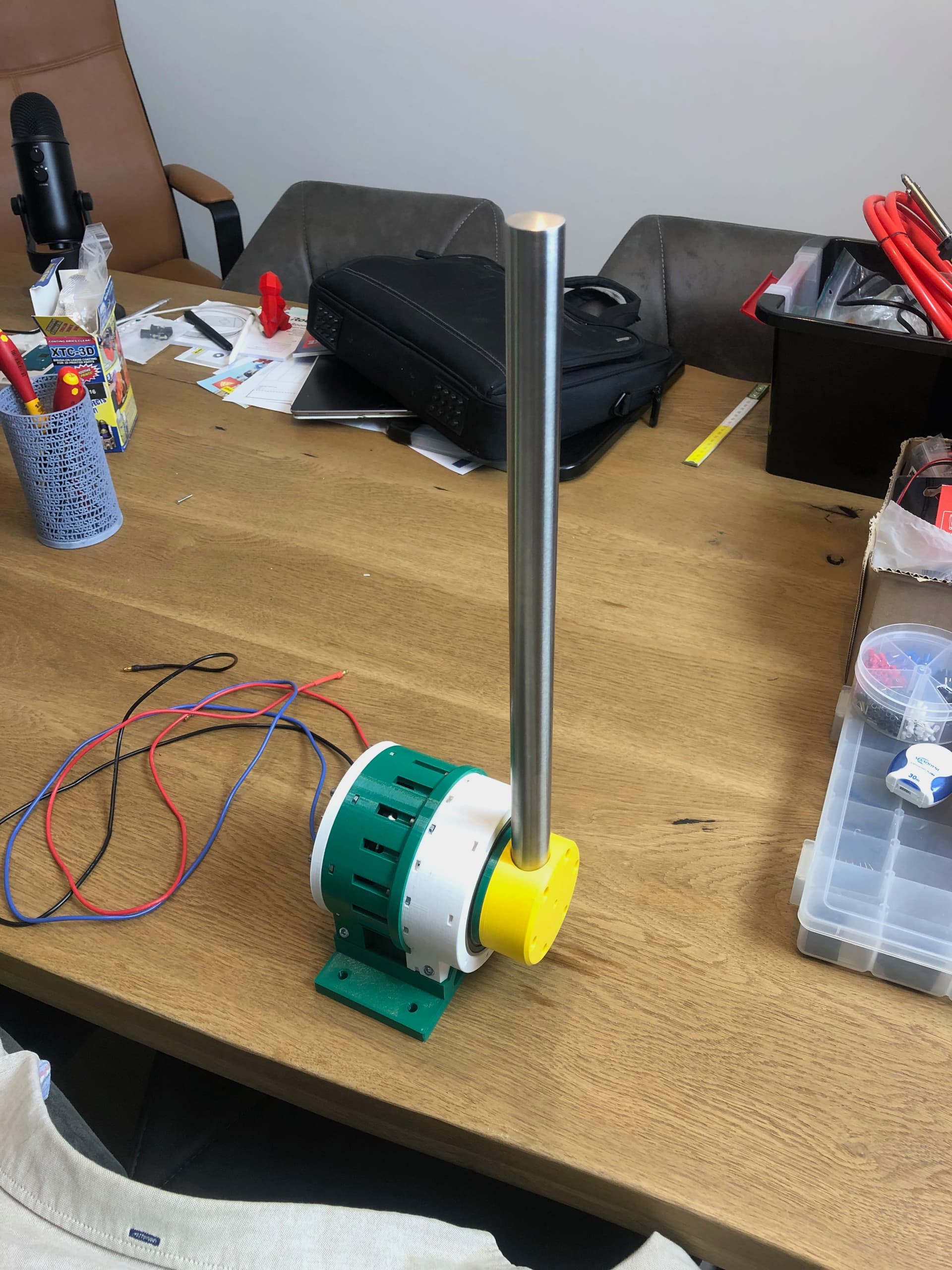
I did not progress a lot on this project myself, but I plan to pick it up again soon. But I did attach a big rod to the motor (fun fact: its actually a part of a toilet roll holder, and it is not nearly as strong as it looks)
Hello !
First of all I really like your new design from the Open Torque project !
I had the same problem as you with the OpenTorque project: the price / rarity of a cross roller bearing.
I was looking for an Actuator to do my new project of doing a quadruped. I need something low cost! ^^
(I will use 3 Actuators per leg)
I have finished designating the leg (it is normally fully 3D printable, but I haven’t print yet…).
I ordered everything you recommend in your first post to make 3 OpenTorque. I’ll receive everything on February …
As you said, the cross roller bearings were there to support lot of axial and radial forces. I’ll test if it’s possible to use your design version for a “robot arm”.
If that does not work, I would reinforce with a second point of support (as I did on my shoulder design).
I’ll keep you informed if it works or not
Thanks for your work!
(sorry for my bad english ^^ I hope it’s readable anyway)
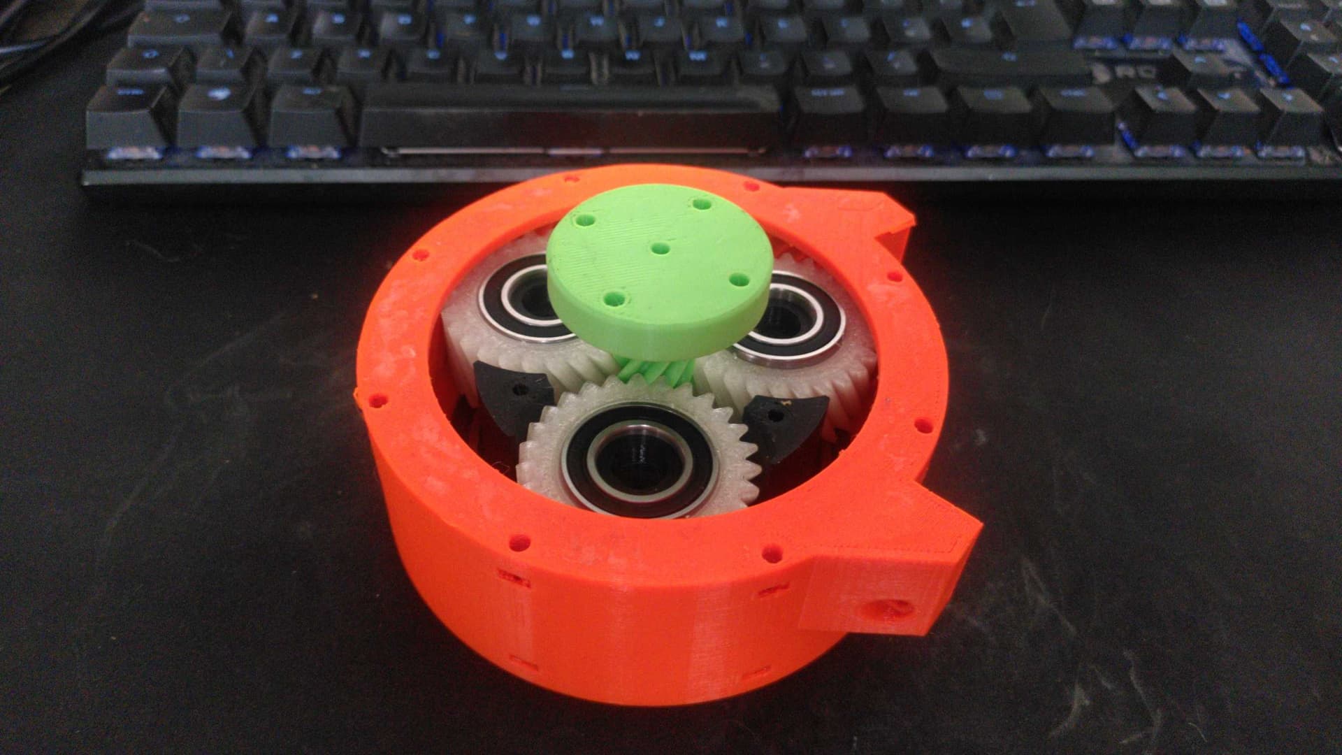
thanks for sharing your design! I have just finished printing one
Since I use a smaller motor and a MJBots Moteus for motor control, I have redesigned some things.
I adapted the sun gear to the other motor and the planet carrier.
Because the motor does not build up so far, I had to adapt the housing as well. The actuator is now about 10 mm less high.
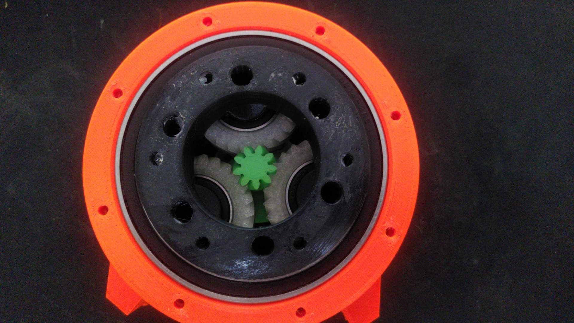
The backplate, where normally the encoder is mounted, I adapted to the Moteus board.
I printed everything in PETG. All gear parts, however, with carbon reinforced.
I had problems because the gears are a bit tight. This is mainly due to the ring gear and the filament used. With a different filament, the gear was much smoother. With a little post-processing, however, it worked.
The gear can be easily moved by hand and I can not detect any backslash. However, moment peaks can be felt during the movement. It could just run smoother. Does anyone have a tip for me to minimize this?
Hi there, I was wondering if the motor you adapted it for is the MJ5208 from MjBots. I have the same motor and I would like to 3d print this transmission, so it would be great if you could share your design!
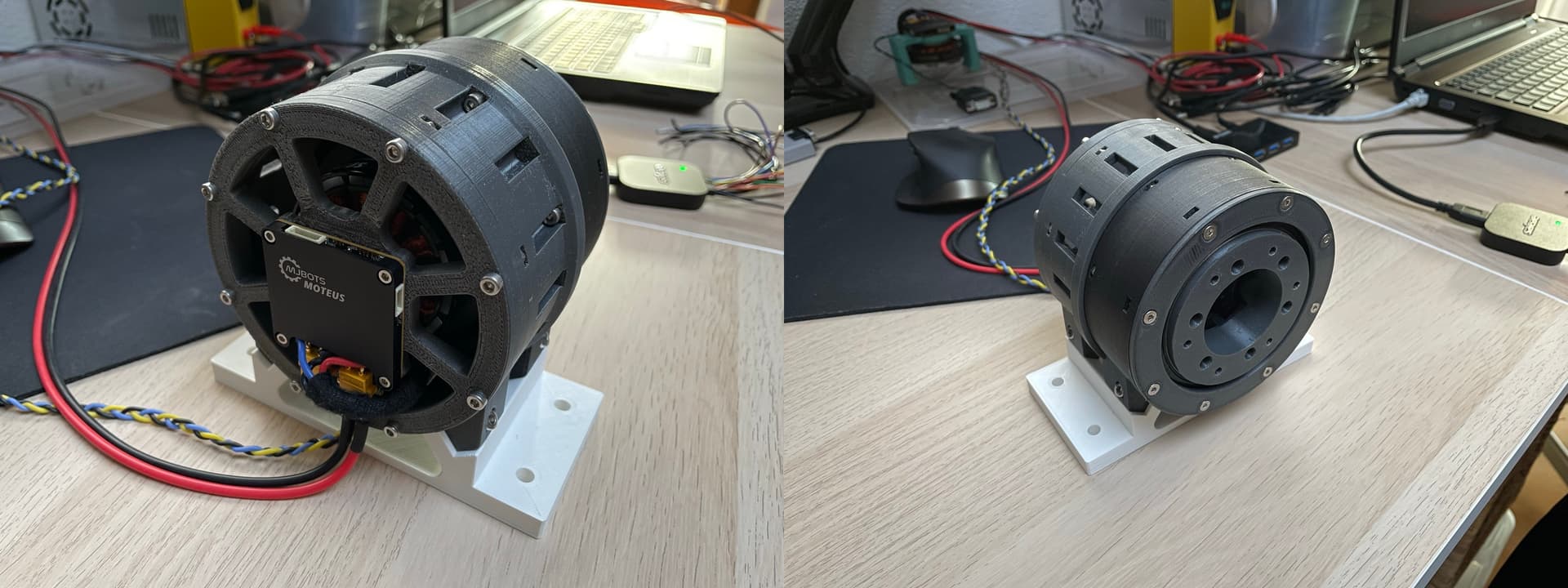
Hi @acisre, your actuator is working really well I must say. I have tested it so far up to 18 Nm which is pretty impressive.
However, I have two pieces of feedback:
One, the M4 nuts inside the planet carrier can sometimes seize on the end of the screw, and then start to spin in place, meaning that the screw will not go in and it is almost impossible to remove the screw. I found a (horrible) way to remove it using a drill, spinning it and applying tesnion so that it melts its way out, at least it’s not destructive to the rest of the part… I printed in PETG, so maybe the seizure is caused by stringing. Do you have a way to avoid this?
Two, would it be easy for you to make a version for 8308 motors?
These motors are very similar, except 10mm shorter in height. I printed an adapter piece to use the 8308 in the big actuator, like bernhard did for the little mjbots motor, but it would be great if the actuator itself could be made shorter. This is a lower torque motor so you could reduce the length of the planet gears by half or more (and only use one bearing in each) which should also reduce friction by about half.
Then obviously you could reduce the motor housing by 10mm, so overall the actuator should be about 20-25mm shorter, but the same diameter.
I am going to look into this. Not sure if I completely understand the first issue, and also not sure how I could solve it… Could you include a picture that shows the issue? I probably need to design a different way to insert the nuts, or perhaps make them a bit bigger (M5 or so…)
I will take a look at the 8308 motors and your remarks about making the planet gears shorter. That should not be a lot of work… It will only cost you my right to ask you a stupid question about motors in the future
The fact that it can reach 18Nm is still to the credit of the original designer of the actuator I should add, I just updated it with some new bearings. Glad it is working well!
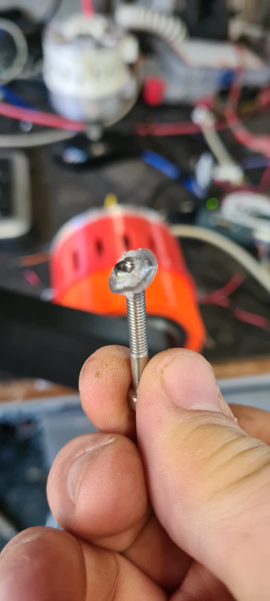
This is after I have removed the stuck screw with the drill.
So you can see that the screw went fully into the nut (so it is not cross-threaded) but for some reason the screw and nut seized together, and the nut then rounded out its slot.
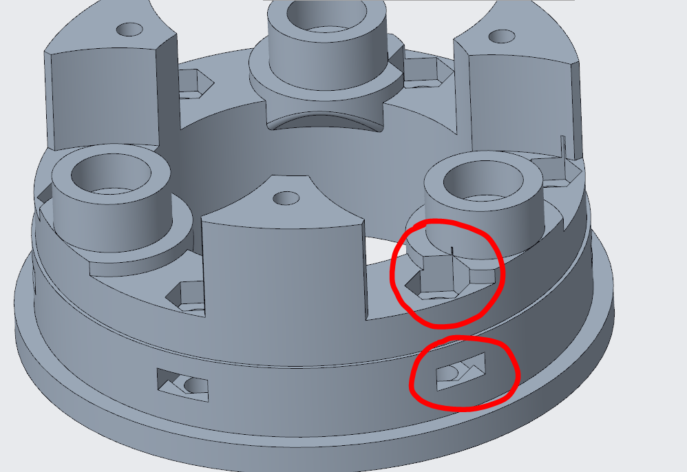
One thing you might try would be to put a full hexagonal pocket , like this:
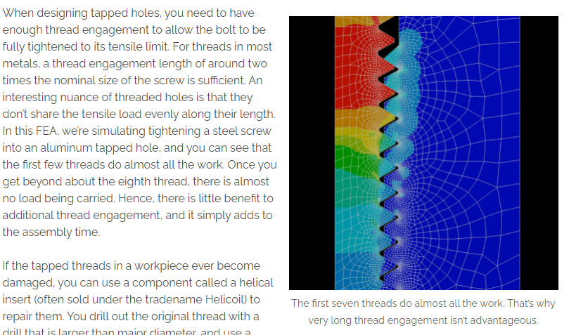
Alternatively, I wonder if a tapped hole might actually work better than a captive nut here, since there’s plenty of depth for the thread to grip into.
Nice, thank you!
BTW, someone has made an incredibly detailed model of the 8308 motor that might be of use to you.
My motors are identical except for the hex nut at the back.
the model of that 8308 had some problems, you will see when you open the step but I think everything should work (even though I did this one really fast)
to be tested…
I did this, and also added another pocket for a nut on top, so you can choose.
Perhaps this is a bit different in PETG, but besides the theory I am also a bit lazy and prefer to just use nuts to avoid all the work of threading the holes
So, the updated side pockets seem to work really well - no fouled screws yet.
However, I’m not so sure about the hex pocket on top.
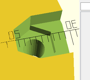
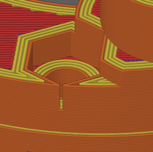
For one: Even with a 0.2mm nozzle there is a tiny gap:
And for two, there is only about 2mm of tolerance in the screw length: too short and it won’t go into the nut, too long and it will foul against the gears
And for three the nuts fall out, making it really hard to assemble that way.
ok, let’s remove the pockets on the top again I also prefer side pockets because you can not push the nuts out of them… With the top pockets you would need to use hotglue or something else to keep them secured.
By the way,I also found an interference with the stand, so I updated this model (stand.stl) as well…
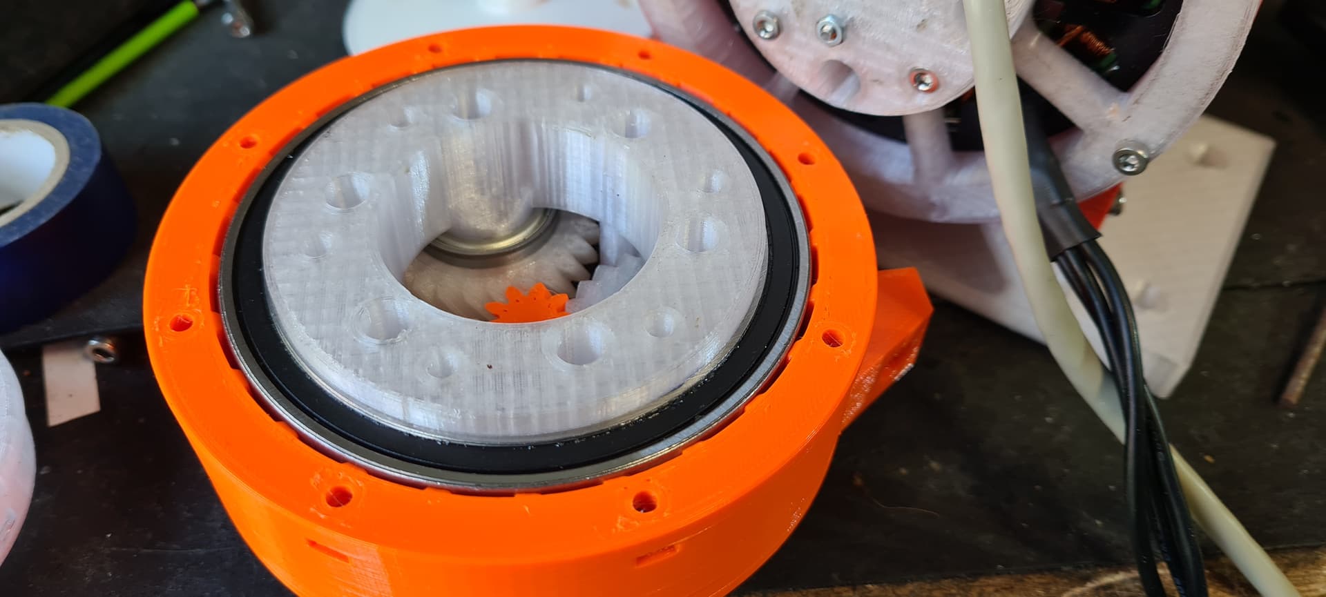
Nice. Btw I have found one more small-ish snag with this design, which is that with only one bearing per gear, the planet gears can now come slightly out of their bearings. Maybe some glue would help, or else maybe since I am using flexible TPU, I can put a small lip on the open side of the gear and then stretch it over the bearing.
 I have nearly finished printing one of my own.