Our 4-axis robot arm diploma thesis

Hi there,

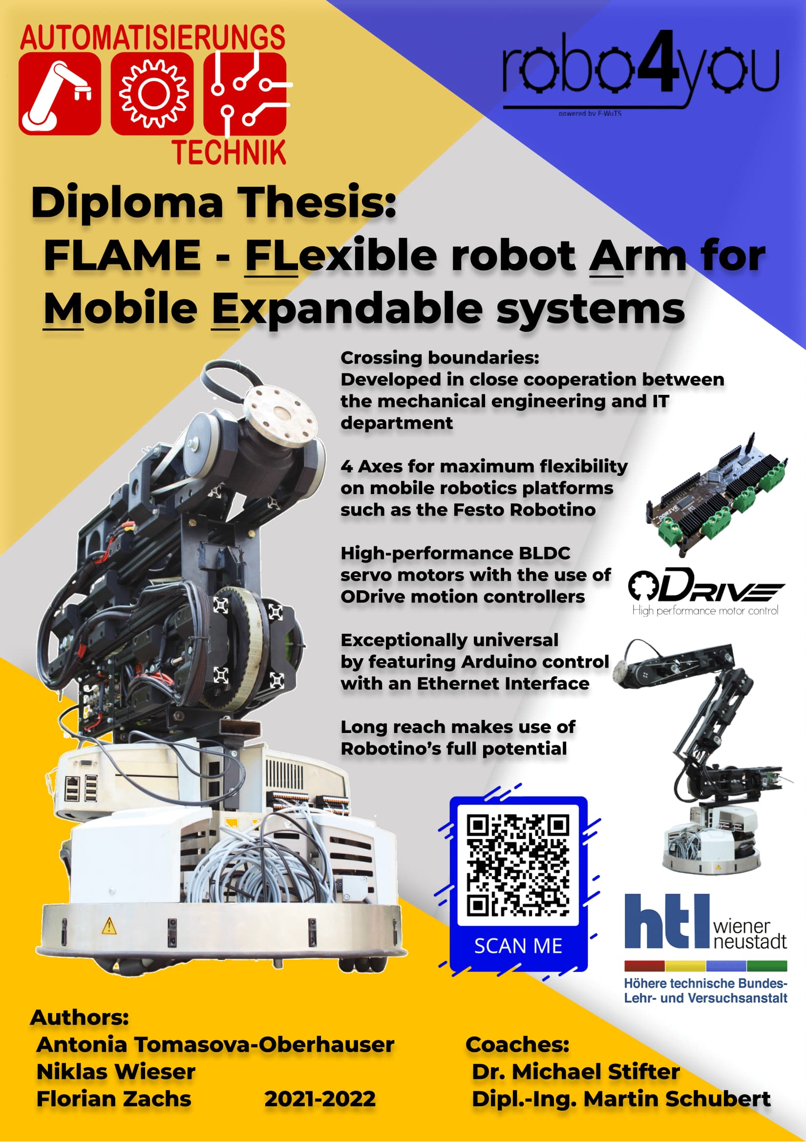
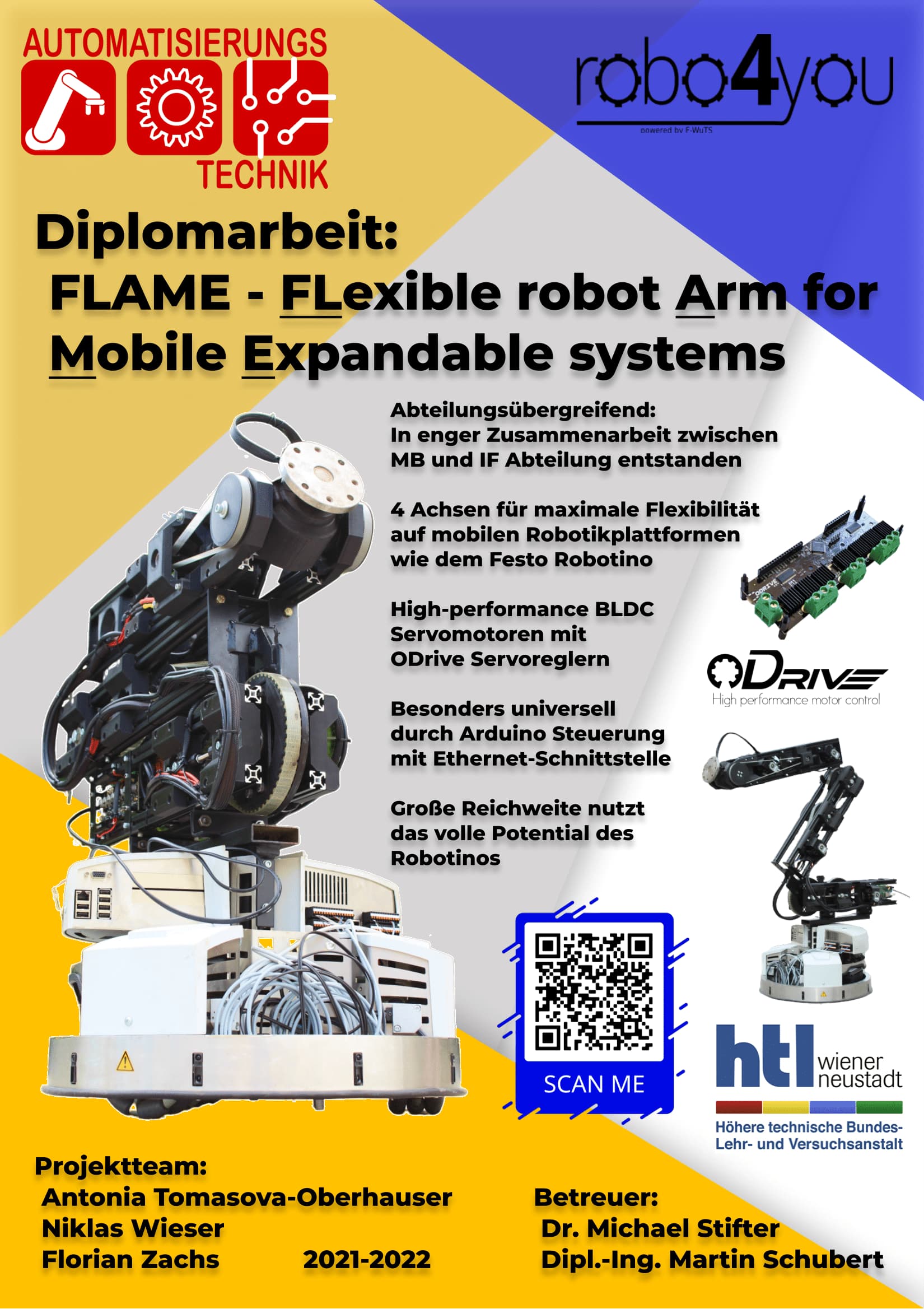
i would like to share our project, because I think it’s quite interesting and might help someone getting started. It’s our diploma thesis project for school, it’s hopefully going to be finished soon.

The entire robot arm was developed from the ground up with a budget of around 1500 to 2000 Euros, but the less the better. ~800 Euros were spent for all ODrives and motors and electronics, ~80 for the aluminium extrusions and the rest was spent on little things like bearings, screws or 3D printing filament, all in all we spent around ~1200 Euros I think.

The 3D model

Here you can see the current 3D model, modeled in Creo Parametric:

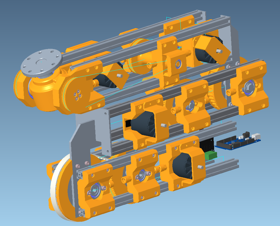
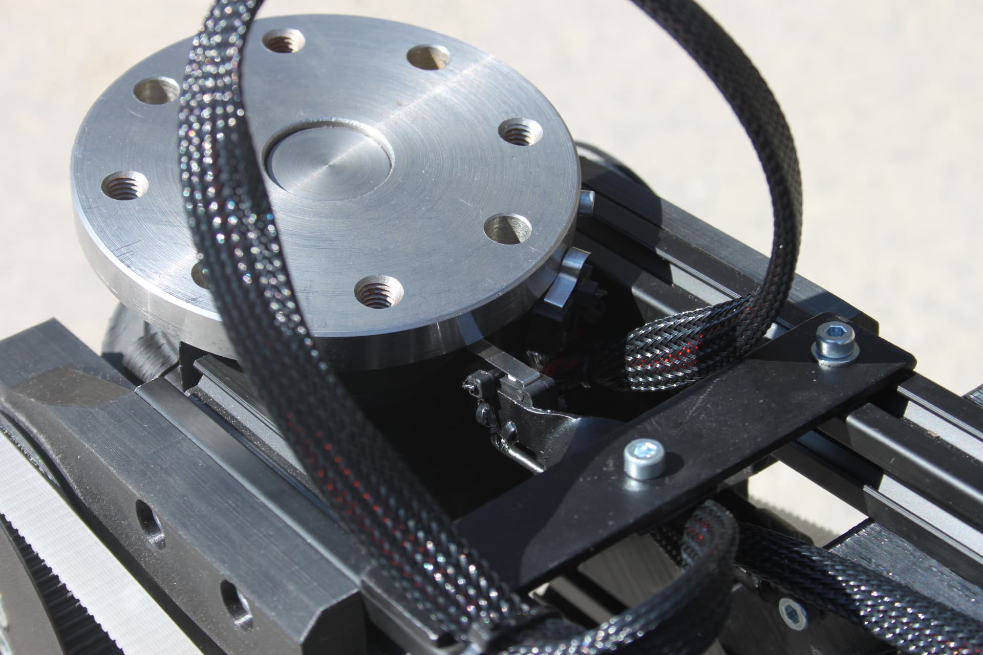
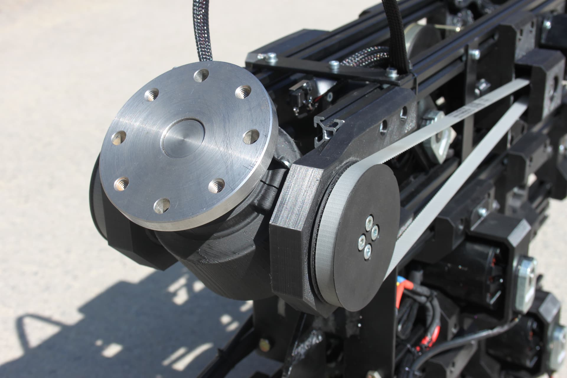
It has 4 axes, 3 are in a plane, I think you can imagine how it works. The fourth axis is the rotatory plate on the top. It’s a universal adapter plate and you can attach anything you want to it.

Festo Robotino

This robot arm is meant to be mounted on top of a Festo Robotino:

This is a mobile industrial robot from Festo, and it’s specifically developed for education and research. It is most often used for things like navigation or implementation of SLAM, which is a pathfinding system which uses a LIDAR sensor and generates dynamic point cloud maps on the fly, in other words it can navigate in unknown environments, even if something changes over time.

Our plan was to develop a robotic arm on top of it, which allows it to manipulate things and take part at international robotics championships for a comparatively low price.

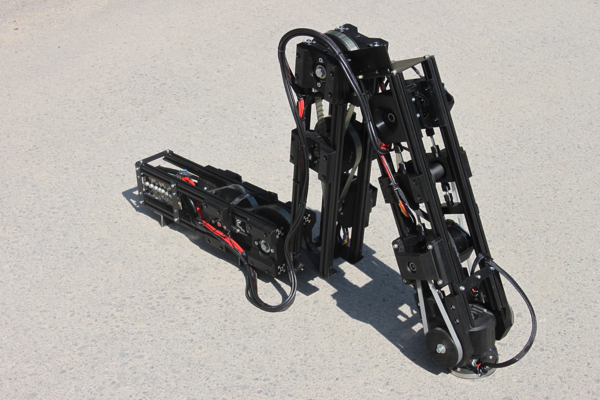
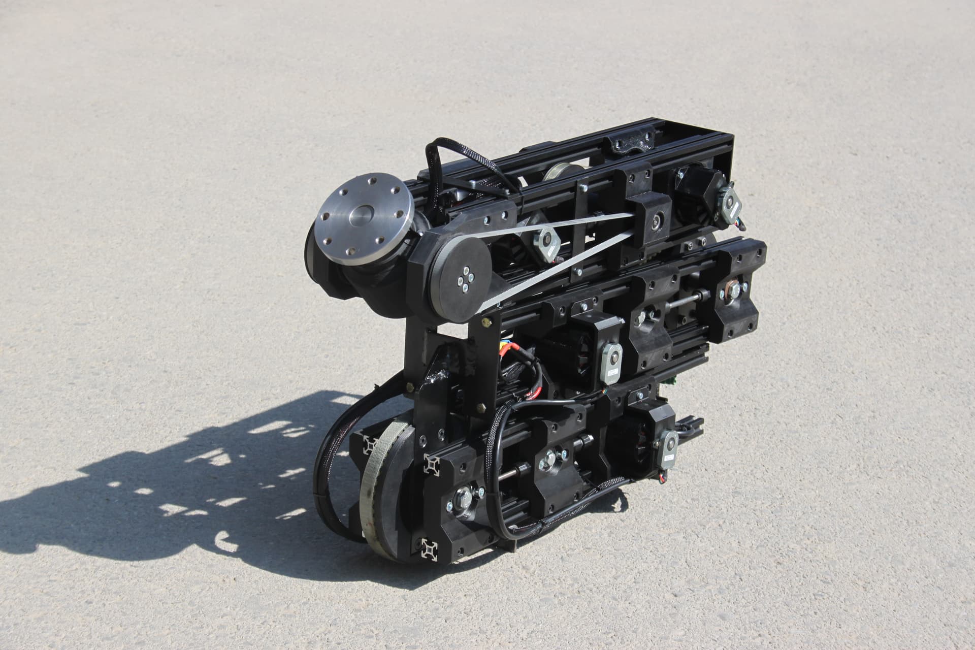
Here you can see a side view of the robotic arm:

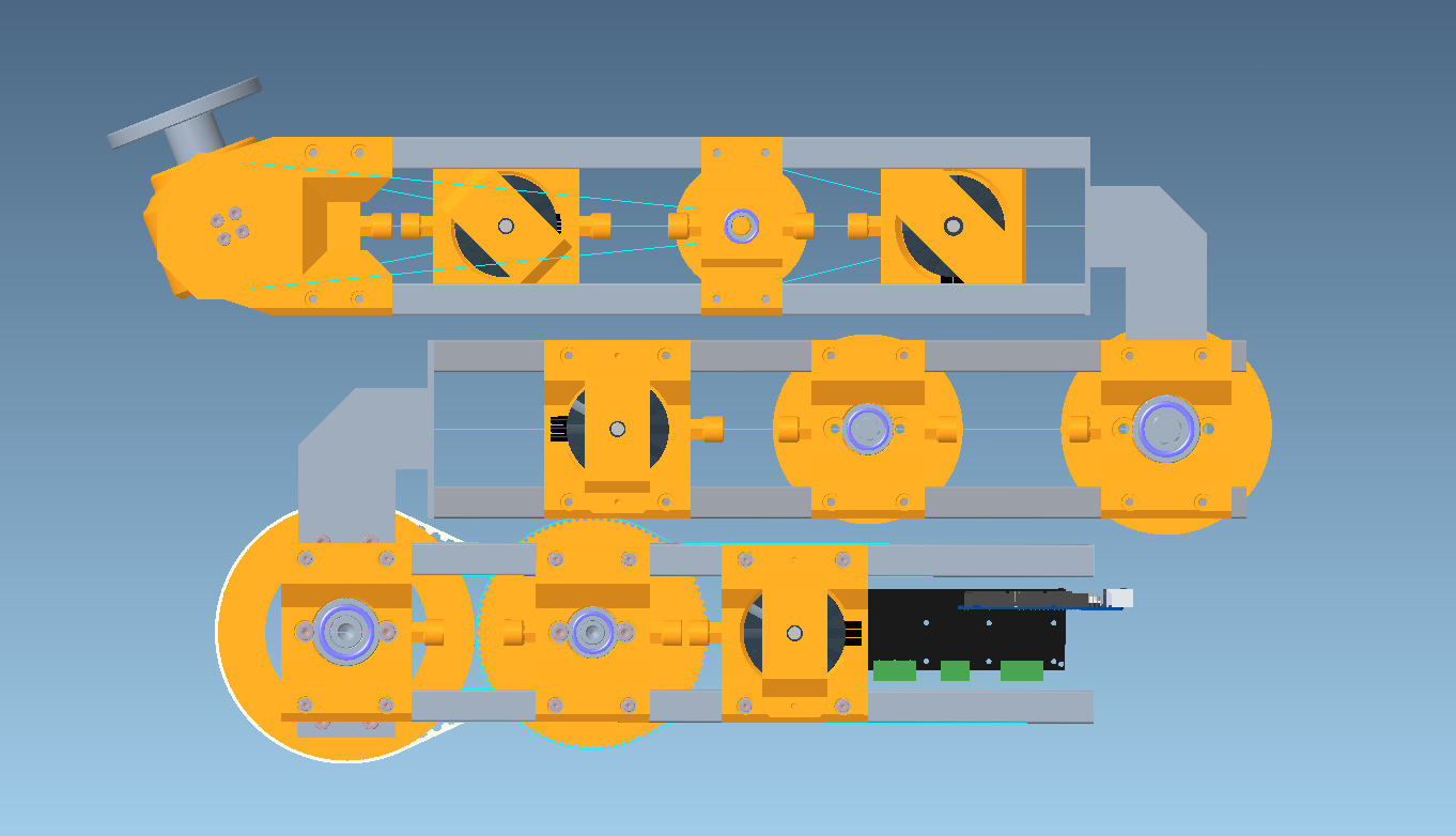
I hope it’s clear where the joints are located.
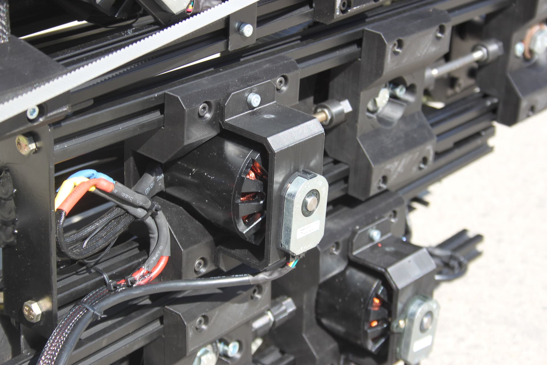
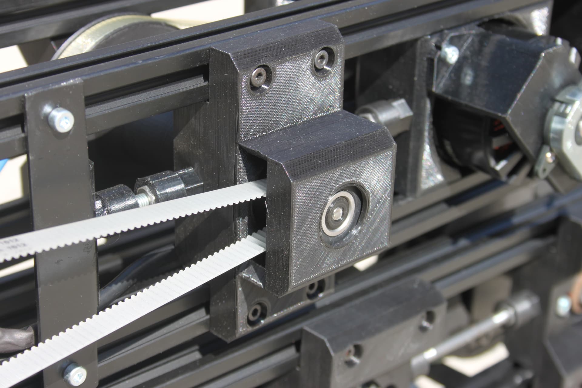
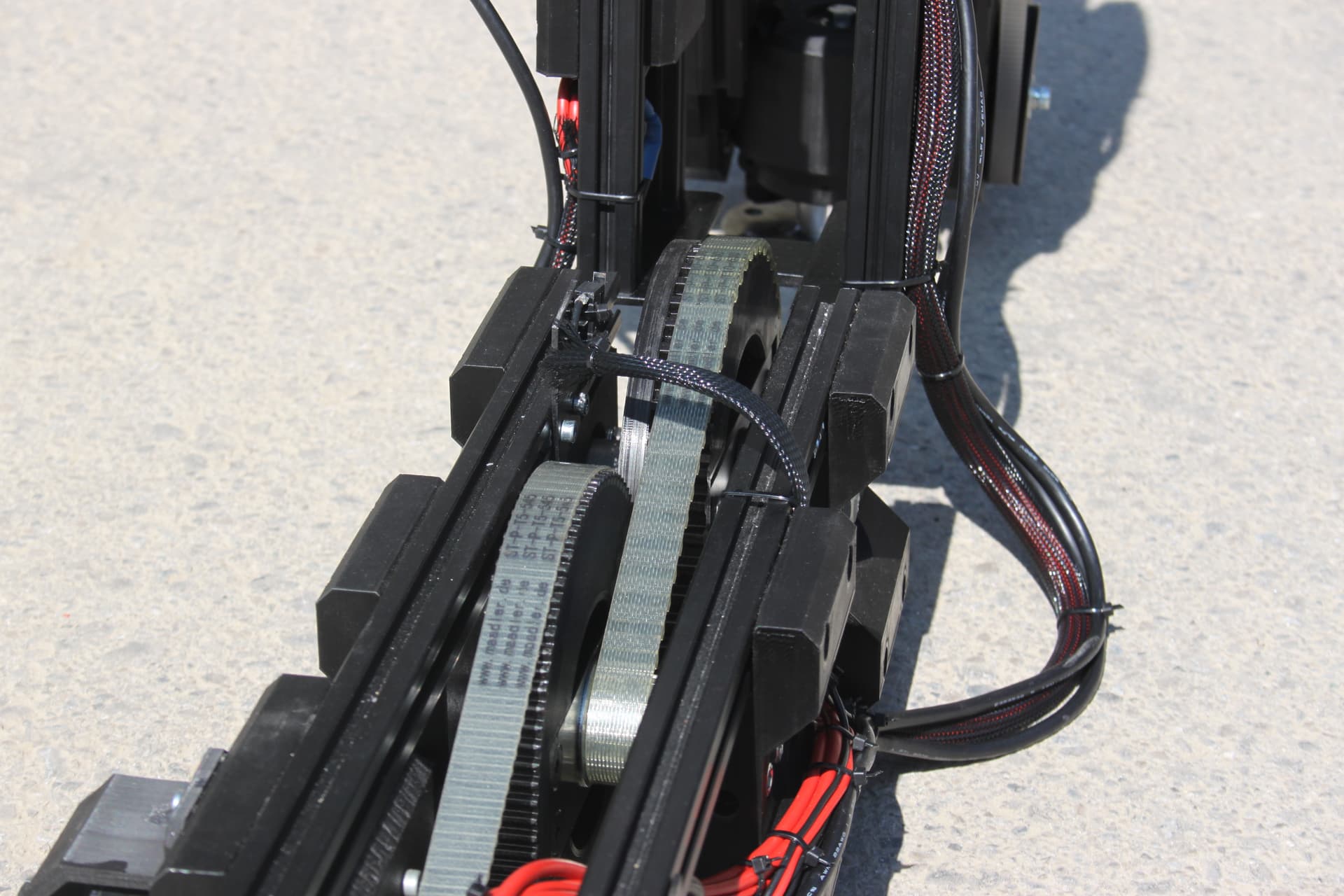
Everything is driven by tooth belts, the first axis has a reduction ratio of 1:25, the second 1:16.

The third axis is the entire orange casing where the fourth axis is mounted on and the fourth axis is the adapter plate.

All orange parts are 3D printed.

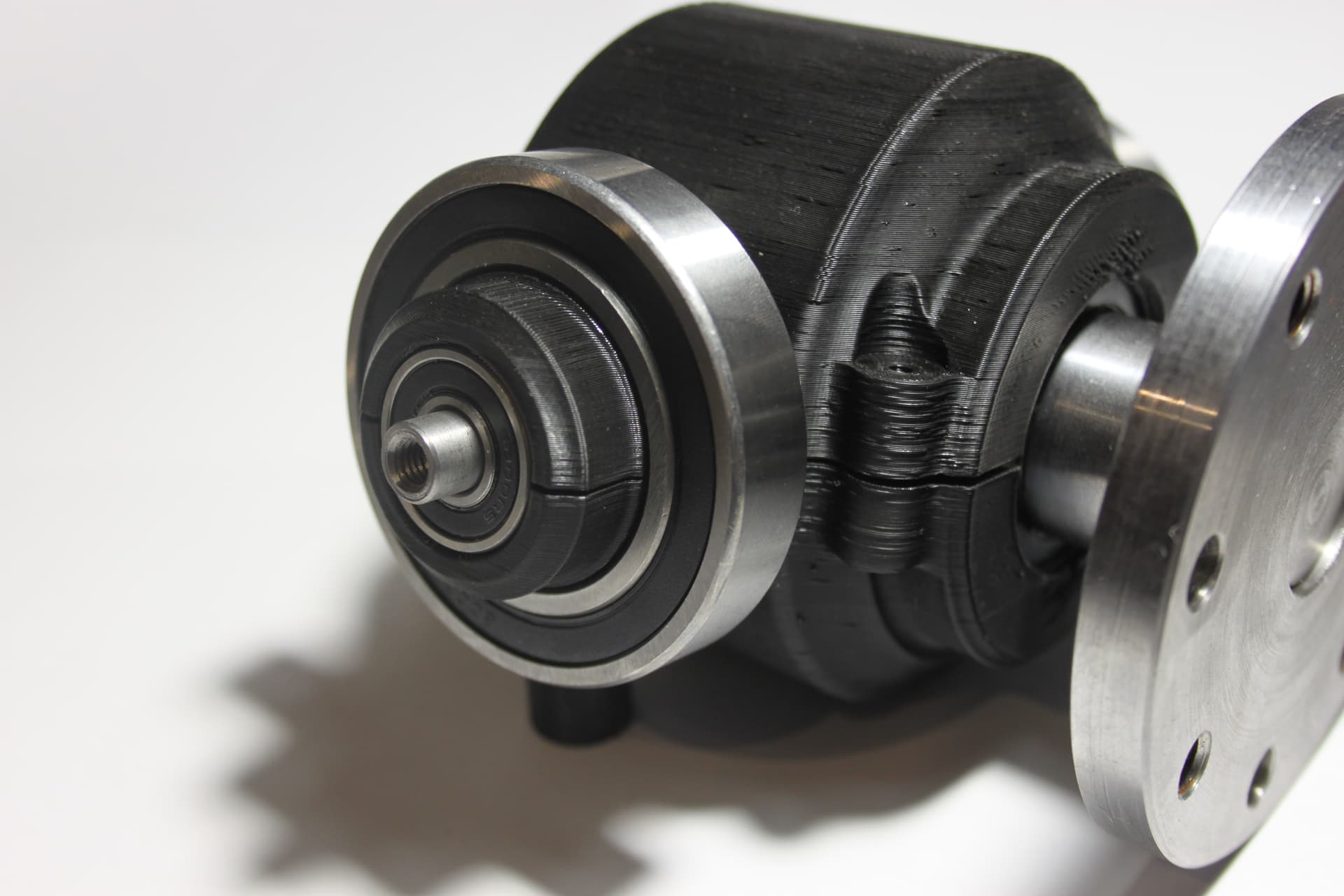
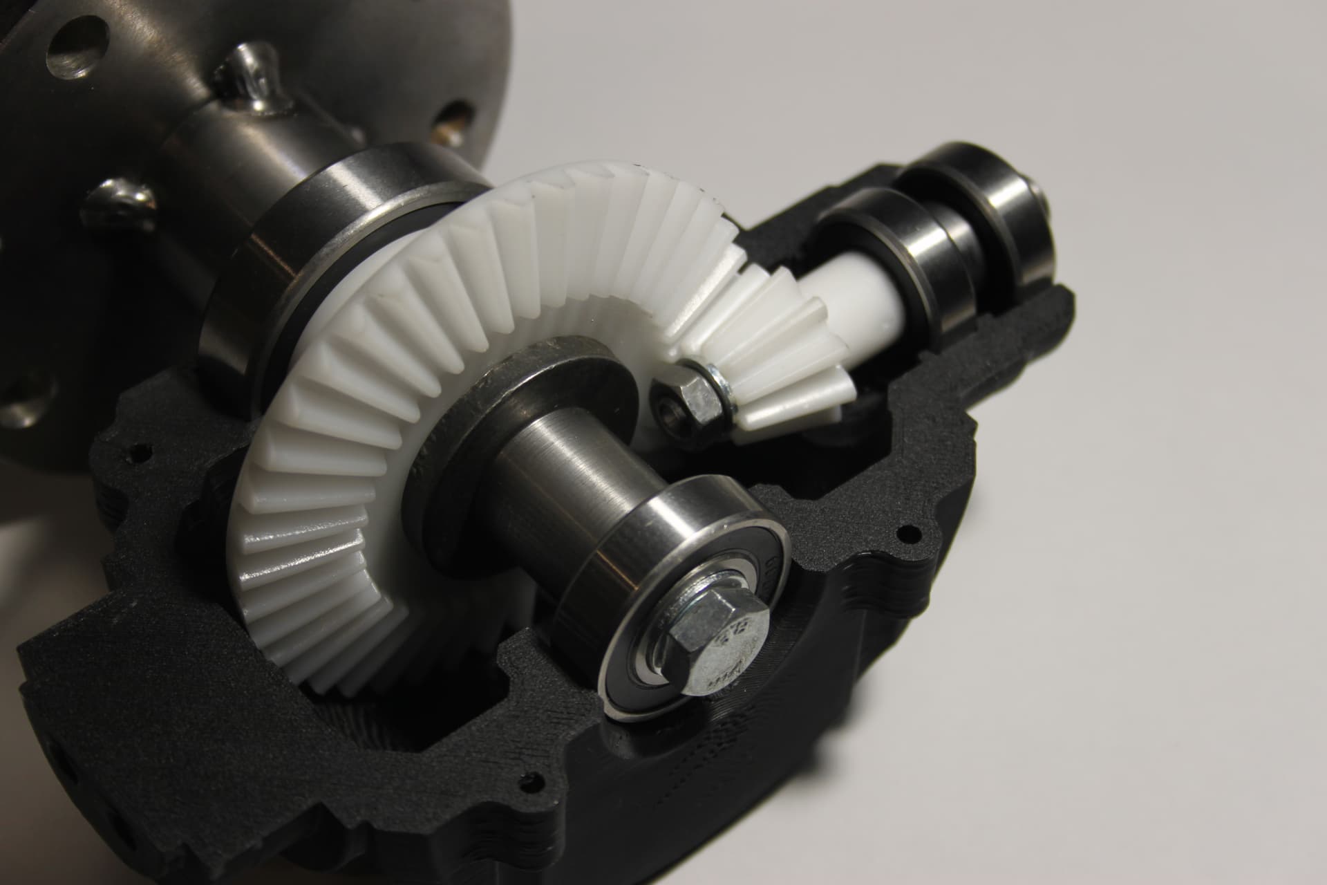
Here’s a cross section of axis 3 and 4:

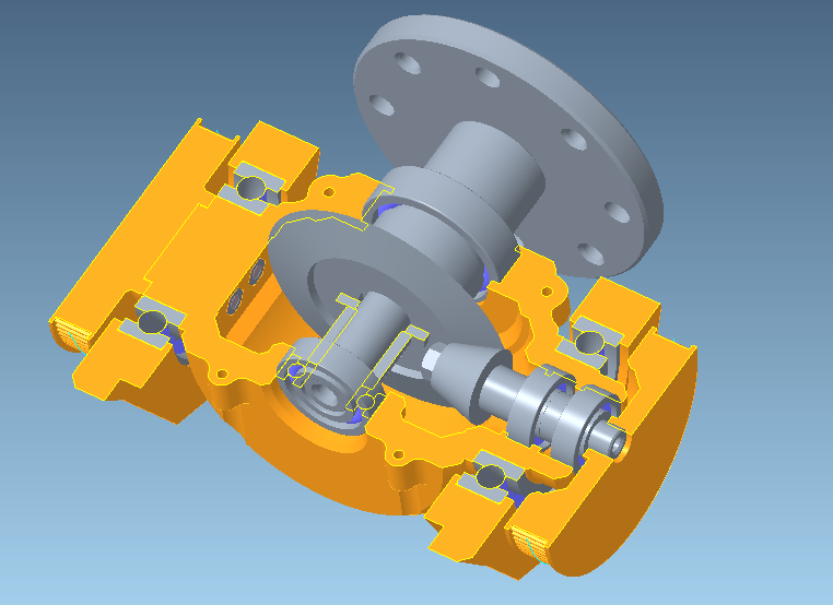
This was the hardest part. The left pulley is mounted directly on the casing, which rotates it and the right pulley is led through into the casing, driving a bevel gear, which drives the fourth axis. This results into that when the third axis is supposed to be moved, axis 3 and 4 need to be moved at the same time. In other words the position of the third axis needs to be added to the fourth axis.

If you were to turn the left pulley, but keep the right pulley stationary, then both axes would move.

The logic

The 4 motors are controlled by 2 ODrives. They are controlled by an Arduino MEGA 2560 with the UART Native protocol. Because of that we have to use Firmware v0.5.1 because all newer versions have a bug which make UART native unusable, but with v0.5.1 it works.

The Arduino is the head of it and controls all 4 axes of the 2 ODrives. On the other side it’s connected to an SPI Ethernet adapter, one of these:
image

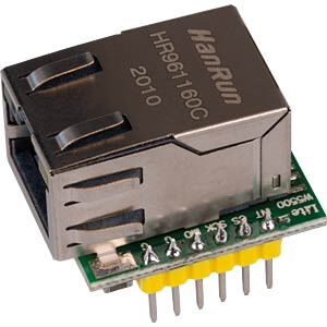
They work surprisingly well and incredibly fast. This way you can simply connect any PC to it and control the entire robot arm with a single Ethernet connection. We used a self-defined protocol which is very simple. It uses UDP/IP and simply sends very basic packets in regular intervals. The trajectory is calculated on the client PC and is streamed to the Arduino, so the packets include the target position and some other information and is streamed at an interval of 100 to 1000 Hz. We will have to do more tests to find out what frequency is really necessary, but I think around 200 to 300 Hz will be it. Then the PC streams data to the Arduino and the Arduino streams other data back to the PC and both streams are independent, timing-wise.

Since I created a very simple Inverse Kinematics and it turned out to be so simple, it will be done on the Arduino. I’m going to describe the IK in a separate post later.

That way the client PC on the other side of the UDP connection simply streams the x and y position, as well as the rotation of axis 3 and 4. The Arduino will then do the inverse kinematics, which makes the logic on the client a lot easier. The client will simply be a PC with a C++ program, which discovers any available robots with a UDP broadcast and then connects to it.

On the client there is a C++ library developed, which allows any new user to very simply for example change the y position in a loop, and a background thread will do the UDP streaming. Due to the IK on the Arduino the robot will move in a straight line up.

The goal is to make it as simple as possible to use, so that new users in the future will be able to control the robot arm without knowing anything about it.

Presentation

For our diploma thesis project for school we need a short video of it working, which simply shows everything. When everything is finished we will probably mount it on the Festo Robotino, use a laptop next to it or use the Robotino directly for the UDP host, depending on if it’s fast enough, we haven’t tried yet. Otherwise everything would be done on the Laptop, which controls the robot arm and the Robotino.

When it is mounted on the Robotino we will probably mount some sort of forks onto the adapter plate, which will then take up cardboard boxes and stack them, just to show that it is working and that the inverse kinematics are working.

Well, that’s mostly it.

That’s the most interesting things I can think of currently, but I have probably forgotten a lot. If you’re interested just ask something, i would be glad if I could help someone. More images of the real thing will follow when I get to do it.

Let me know if there’s something you would like to know!

4 Likes

The Festo Robotino 3 which we use is basically a self-contained PC running Ubuntu. There is a version of it that has an Intel i5 CPU, but ours only has an Intel Atom. It’s not much and certainly not enough to run SLAM, what it’s most often used for (described above), but it’s enough to run basic programs. The Robotino hardware is controlled from this embedded PC with a few libraries and daemons. Everything is network based, so it can be controlled from the embedded PC itself via localhost, or from any other PC that is in the same network.

So, to recap the Robotino is a fully functional PC itself, but doesn’t have a lot of processing power. I think it’s enough for us, tho, so we could simply run a C++ program on the embedded Ubuntu, which controls the robot arm and the Robotino itself. Otherwise the same C++ program would run on a separate Laptop, because everything is network based it makes no difference.

1 Like

Looks very nice!
Where is the second ODrive mounted? Where are pictures of the real thing? :slight_smile:

Thanks!

The second ODrive is not modeled currently. The electronics were just imported and they are actually just floating in space right now. However, in the real world the first ODrive is mounted sideways just like in the model with the delivered black plastic standoffs and the second will be stacked on top of it with the spacers. I don’t yet know where I should mount the Arduino and Ethernet jack. I’m going to do that when most of the arm is finished.

Currently we are printing a lot of parts. When i get some of them I will assemble some and then I will take good looking pictures, that will probably be in 1 to 2 weeks, so please be patient :slightly_smiling_face:

2 Likes

Alright, I think it is time for some photos. Is is basically finished, only the arduino needs to be mounted, as well as the brake resistors. Otherwise it should be finished. Unfortunately it doesn’t move yet, it is still a long way to go software wise. Nevertheless, here are a few photos in case someone is interested:


It is only standing on the streets, it’s not mounted on the movable robot yet.
What do you think?

4 Likes

Actually, you can just download and read it here:

Unfortunately I had to host the file on Github because I cannot attach pdf files. Just click on Download

3 Likes

Looks nice! I love the limit-switch on the tool end
What is its stiffness in the driven (under position control) and non-driven (sideways) directions?
I.e. if you pull the end of the manipulator out of position with a spring balance, can you plot force vs displacement?

2 Likes

Looks pretty good! Now only a video is missing, showing it in action :wink:

2 Likes

Phew, this is something we might test later when it is finished and mounted on the Robotino, controlled with an XBOX controller. My current plans are to control the Robotino with the XBOX controller and then switch to arm-mode with a button, and then control the arm position with the controller.

We have to prepare it for presentation until june, I hope we can finish it in time. Then we might do such tests if we don’t forget and can actually get a hand on a spring balance :slight_smile:

I would suggest that the stiffness is actually pretty important to getting the thing up and running.
(actually you can calculate the controller stiffness from the gains, gear ratios and motor constant, but it is good to verify it with the spring balance - the difference of course will be the mechanical stiffness of the arm)

Before you connect your XBOX controller, you should place it into position hold with a low current limit and tune the gains. Then gradually increase the current limit, while verifying that it can move between two set positions.
The controller stiffness should not exceed the mechanical stiffness, otherwise you will run into some serious dynamic instability.
Next, you will have to ensure that the system is stable across the full range of both axes, with and without load. You can maybe do that with your Xbox controller, if you are careful.

Do you have any kind of emergency stop on this thing? I see some mention of one in your writeup, but it sounds as if you are simply stopping sending UDP packets. That will not be enough to stop the arm if the position controller goes into an uncontrolled oscillation. So I’d at the very least suggest that you should enable the watchdog so that as soon as you stop sending position updates, it will stop the arm.

Ideally though you should have a quick way to cut power in case that doesn’t work. I wouldn’t want you destroying your project, or worse, hurting yourselves with it.

Thanks, this is a good hint.

Currently the Arduino has a timeout and when no more UDP packets are received, it enters safety mode and does not accept UDP position commands anymore until the client synchronizes the position and unlocks safety mode again. Currently, there is no additional protection between the Arduino and the ODrives.

This is another thing I didn’t know, I might implement this when I get to it as it could protect the arm when the Arduino crashes or gets disconnected.

But you are right, I should add a proper emergency button to the arm which is connected to the Arduino and both ODrives.

As the last step in this project I had to create banners for my diploma thesis for my school, so that’s what I did. Since I have them done now, I thought it was a shame not to show them so here they are in case anyone is interested:

This will probably be my last contribution to this project, but if anyone is interested in it or in similar projects, just contact me, I am always open for project ideas.

3 Likes