Phase resistance out of range (3.2 Ohms)

Hey,

I wanted to drive a (geared) bldc motor that i salvaged from a robotic lawn mower, after some research I bought an Odrive 3.6.

Note: I removed the gearbox for all of this. Just the bare motor.

Motor main facts:

  • 10 magnets / 5 poles (spools are on the outside, magnets in the core)
  • 3 hall sensors
  • 24 - 48 V
  • 73 KV
  • 3.6 Ohms per phase / 7.2 Ohms over two phases

I pretty much followed the hoverboard guide because the motor seemed somewhat similar, only replacing KV and cpr (I used 30 here).

I am currently supplying 36V / 2A from a benchtop supply.

When getting to the calibration step, the motor does move a few milimeters, then stops. The error log shows “PHASE_RESISTANCE_OUT_OF_RANGE”. The resistance reads 0.0, inductance nan.

After a long time googling, I read about the limit being 1 Ohm and a few attempts from rising the resistance range via the cli to changing up the low_level.cfg.

Most of these posts were from around 2017. Are there any more comfortable ways by now?

From the Odrive Discord I got the hint to try the gimbal mode, which resulted in nothing happening when trying to calibrate, but no errors.

So: With my 3.6 Ohms phase resistance, is Odrive even going to work for me? I am looking for a somewhat reliable method of driving these. There is no need to keep a specific speed or position. They are just driving a lightweight box like an rc car. Noise is not an issue.

Here is a graph I got from the manufacturer:

Have you tried increasing motor.config.resistance_calib_max_voltage?

Yes. I tried increasing from 4 (as suggested by the hoverboard guide) to 6. I was hesitant to go further. This was mainly tried in MOTOR_TYPE_HIGH_CURRENT.

In gimbal mode, the resistance calibration current refers to a voltage, just like the current limit.

Overall: Should I go with gimbal mode with my motor or with high current mode? What setting should I try with the calibration current and current limit?

I am quite new to driving motors.

I’ve received another piece of information if that helps:

How big is this motor? Any idea what its power rating might be? Is it designed for low voltage or mains voltage?
Unless it is a big, powerful motor that will handle a few amps into that winding, then the ‘high current’ mode is not going to work, unless you were to make the hardware & firmware mod that involves changing the current measurement shunt resistors.
ODrive is designed to work with motors with continuous current ratings in the range 5A-100A. Your motor would produce 100W of heat at 4A, so even if it is big, it’s probably going to overheat before it registers on ODrive’s current sensors.

So probably for this motor you will need to use gimbal mode… For resistance calibration, you can safely go to 2x the power rating of the motor for calibration, since it is only a short pulse.

The motor is rated for 24V to 48V and is usually driven by a 42V battery.
From the manufacturer’s info, the current draw is about 2 to 5 A @ 24V.

It’s used as a geared motor, but the gearbox does not come from the motor manufacturer. I am currently trying to run it without the gearbox attached.

It’s 48mm in diameter. Here is also an image where I cracked one open.

I followed this guide to test the resistance (in my case I could just measure it with a multimeter tho). If I limit the bench top supply at 3A, it puts the voltage to around 21V. 21 V / 2 Phases / 3 A = 3.5 Ohms.

Does that mean, that I would need to put the calibration current to 3A and the calibration voltage to atleast 21V?


You can leave the calibration current at a normal level (say 1A) - this is used for the encoder offset calibration, where the motor moves back and forth in open-loop microstepping. ODrive will pick an appropriate voltage to use for that once it has measured the phase resistance.

The only thing you should have to change is the resistance_calib_max_voltage - put that up to 20V and see if it successfully measures the resistance and inductance (AXIS_STATE_MOTOR_CALIBRATION).
Then make sure it is in Gimbal mode and do the rest of the setup (AXIS_STATE_ENCODER_OFFSET_CALIBRATION).

Hey,

this got me a bit further as I am now able to calibrate the motor without any errors. I get the beep and also a somewhat off measurement for the phase resistance (ODrive measures 2.3 Ohms. In reality it’s around 3.6 Ohms)

odrv0.axis0.motor after doing AXIS_STATE_MOTOR_CALIBRATION

In [84]: odrv0.axis0.motor
Out[84]:
DC_calib_phA: 1.1101914644241333 (float)
DC_calib_phB: -1.0377676486968994 (float)
DC_calib_phC: -0.07235477864742279 (float)
I_bus: 0.0 (float)
config:
  I_bus_hard_max: inf (float)
  I_bus_hard_min: -inf (float)
  I_leak_max: 0.10000000149011612 (float)
  R_wL_FF_enable: False (bool)
  acim_autoflux_attack_gain: 10.0 (float)
  acim_autoflux_decay_gain: 1.0 (float)
  acim_autoflux_enable: False (bool)
  acim_autoflux_min_Id: 10.0 (float)
  acim_gain_min_flux: 10.0 (float)
  bEMF_FF_enable: False (bool)
  calibration_current: 1.0 (float)
  current_control_bandwidth: 1500.0 (float)
  current_lim: 10.0 (float)
  current_lim_margin: 8.0 (float)
  dc_calib_tau: 0.20000000298023224 (float)
  inverter_temp_limit_lower: 100.0 (float)
  inverter_temp_limit_upper: 120.0 (float)
  motor_type: 0 (uint8)
  phase_inductance: 0.002006554277613759 (float)
  phase_resistance: 2.2909862995147705 (float)
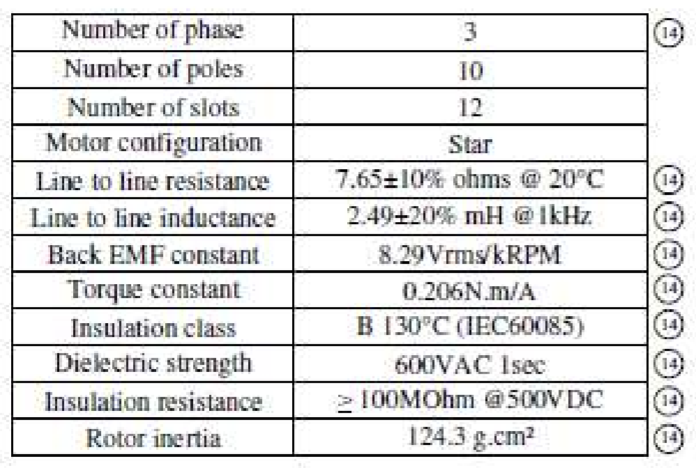
  pole_pairs: 5 (int32)
  pre_calibrated: False (bool)
  requested_current_range: 5.0 (float)
  resistance_calib_max_voltage: 20.0 (float)
  torque_constant: 0.20600000023841858 (float)
  torque_lim: inf (float)
current_control:
  I_measured_report_filter_k: 1.0 (float)
  Ialpha_measured: 0.0 (float)
  Ibeta_measured: 0.0 (float)
  Id_measured: 0.0 (float)
  Id_setpoint: 0.0 (float)
  Iq_measured: 0.0 (float)
  Iq_setpoint: 0.0 (float)
  Vd_setpoint: 0.0 (float)
  Vq_setpoint: 0.0 (float)
  final_v_alpha: 0.0 (float)
  final_v_beta: 0.0 (float)
  i_gain: 3436.4794921875 (float)
  p_gain: 3.009831428527832 (float)
  phase: 0.0 (float)
  phase_vel: 0.0 (float)
  power: 0.0 (float)
  v_current_control_integral_d: 0.0 (float)
  v_current_control_integral_q: 0.0 (float)
current_meas_phA: -1.1066875457763672 (float)
current_meas_phB: 1.0355292558670044 (float)
current_meas_phC: 0.07121540606021881 (float)
effective_current_lim: 10.0 (float)
error: 0 (uint64)
fet_thermistor:
  config: ...
  temperature: 32.445682525634766 (float)
is_armed: False (bool)
is_calibrated: True (bool)
last_error_time: 0.0 (float)
max_allowed_current: 30.375 (float)
max_dc_calib: 3.0375001430511475 (float)
motor_thermistor:
  config: ...
  temperature: 0.0 (float)
n_evt_current_measurement: 415629 (uint32)
n_evt_pwm_update: 415634 (uint32)
phase_current_rev_gain: 0.012500000186264515 (float)

Calibrating the hall polarity also works without an error. While doing that, the motor spins quietly - kind of fast.

In [93]: odrv0.axis0.requested_state = AXIS_STATE_ENCODER_HALL_POLARITY_CALIBRATION

In [94]: odrv0.axis0.encoder
Out[94]:
calib_scan_response: 0.0 (float)
config:
  abs_spi_cs_gpio_pin: 1 (uint16)
  bandwidth: 100.0 (float)
  calib_range: 0.019999999552965164 (float)
  calib_scan_distance: 150.0 (float)
  calib_scan_omega: 12.566370964050293 (float)
  cpr: 30 (int32)
  direction: 1 (int32)
  enable_phase_interpolation: True (bool)
  find_idx_on_lockin_only: False (bool)
  hall_polarity: 0 (uint8)
  hall_polarity_calibrated: True (bool)
  ignore_illegal_hall_state: False (bool)
  index_offset: 0.0 (float)
  mode: 1 (uint16)
  phase_offset: 85 (int32)
  phase_offset_float: 1.4640014171600342 (float)
  pre_calibrated: False (bool)
  sincos_gpio_pin_cos: 4 (uint16)
  sincos_gpio_pin_sin: 3 (uint16)
  use_index: False (bool)
  use_index_offset: True (bool)
count_in_cpr: 3 (int32)
delta_pos_cpr_counts: -5.605193857299268e-45 (float)
error: 0 (uint16)
hall_state: 6 (uint8)
index_found: False (bool)
interpolation: 0.5 (float)
is_ready: False (bool)
phase: 0.0 (float)
pos_abs: 0 (int32)
pos_circular: 0.13250578939914703 (float)
pos_cpr_counts: 3.9750475883483887 (float)
pos_estimate: 0.13250158727169037 (float)
pos_estimate_counts: 3.9750475883483887 (float)
set_linear_count(obj: object_ref, count: int32)
shadow_count: 3 (int32)
spi_error_rate: 0.0 (float)
vel_estimate: 0.0 (float)
vel_estimate_counts: 0.0 (float)

When I get to the hall sensor offset calibration, the motor spins a few times in each direction. After this I get an error: 16 in the encoder config.

In dump_errors(), there is a ENCODER_ERROR_ILLEGAL_HALL_STATE.

In [95]: odrv0.axis0.requested_state = AXIS_STATE_ENCODER_OFFSET_CALIBRATION

In [96]: odrv0.axis0.encoder
Out[96]:
calib_scan_response: 144.0 (float)
config:
  abs_spi_cs_gpio_pin: 1 (uint16)
  bandwidth: 100.0 (float)
  calib_range: 0.019999999552965164 (float)
  calib_scan_distance: 150.0 (float)
  calib_scan_omega: 12.566370964050293 (float)
  cpr: 30 (int32)
  direction: 1 (int32)
  enable_phase_interpolation: True (bool)
  find_idx_on_lockin_only: False (bool)
  hall_polarity: 0 (uint8)
  hall_polarity_calibrated: True (bool)
  ignore_illegal_hall_state: False (bool)
  index_offset: 0.0 (float)
  mode: 1 (uint16)
  phase_offset: 73 (int32)
  phase_offset_float: 1.4663901329040527 (float)
  pre_calibrated: False (bool)
  sincos_gpio_pin_cos: 4 (uint16)
  sincos_gpio_pin_sin: 3 (uint16)
  use_index: False (bool)
  use_index_offset: True (bool)
count_in_cpr: 3 (int32)
delta_pos_cpr_counts: -5.605193857299268e-45 (float)
error: 16 (uint16)
hall_state: 6 (uint8)
index_found: False (bool)
interpolation: 0.5 (float)
is_ready: True (bool)
phase: 1.0823841094970703 (float)
pos_abs: 0 (int32)
pos_circular: 0.13269804418087006 (float)
pos_cpr_counts: 3.97507381439209 (float)
pos_estimate: 0.13250036537647247 (float)
pos_estimate_counts: 3.975010871887207 (float)
set_linear_count(obj: object_ref, count: int32)
shadow_count: 3 (int32)
spi_error_rate: 0.0 (float)
vel_estimate: 0.0 (float)
vel_estimate_counts: 0.0 (float)

I checked my hall sensors with an oscilloscope and they seem to be working. Manually rotating the shaft while observing the shadow_count comes out to be 30 per rotation, which matches my cpr.

After a while I tried what happens if I just keep going and tried:
odrv0.axis0.requested_state = AXIS_STATE_CLOSED_LOOP_CONTROL

Sometimes the motor spins for a second, sometimes for 10 or more while vibrating quite a bit. But it seems powerful.

In [99]: odrv0.axis0.requested_state = AXIS_STATE_CLOSED_LOOP_CONTROL

In [100]: dump_errors(odrv0)
system: no error
axis0
  axis: no error
  motor: Error(s):
    MOTOR_ERROR_UNKNOWN_TORQUE
    MOTOR_ERROR_UNKNOWN_VOLTAGE_COMMAND
  sensorless_estimator: no error
  encoder: Error(s):
    ENCODER_ERROR_ILLEGAL_HALL_STATE
  controller: no error
axis1
  axis: no error
  motor: no error
  sensorless_estimator: no error
  encoder: no error
  controller: no error

I read about adding 22nF capacitors to the hall inputs. I’ll pick up a few tomorrow and give that a try.

I also tried around with the motor types - no difference.

  • Start with HIGH_CURRENT until after the motor calibration, then switch to GIMBAL.
  • Do the whole procedure as HIGH_CURRENT

I am currently running from a benchtop supply that can provide 36V 2.3A max. Should I rather switch over to a 42V e-bike battery?

When giving a quick look to my configs, can you see anything that’s “just off” and wrongly configured?

Did you try the whole calibration in Gimbal mode?

Are you using the ferrite rings?

Try also adding 10k resistors to GND on the Hall inputs.

Your power supply should be fine.

I haven’t tried doing the full calibration in gimbal mode. Gonna try thst tomorrow. Could this be related to the hall sensor problem?

No ferrite rings. The motor wires are roughly 5cm in length. Might give that a try and order them. Would have to extend the wires tho.

I tried adding 10 K pull-ups and also pull-downs while playing around with the halls and the oscilloscope. The sensors seem to be pulling to ground. So having pull-ups seemed to work.

I read that the Odrive pulls up to 3.3 V already. I could still try that if that might help.

Try disabling the check for this. odrv0.encoder.config.hall_polarity_calibrated = True. If that doesn’t do it, then try odrv0.encoder.config.ignore_illegal_hall_state = True. If that’s still not working, then you either have a legit hall sensor issue, or the hall_polarity isn’t set correctly.

My local shop doesn’t have the right capacitors available. I ordered a few + some ferrite rings. Will test this once they arrive.

In the meantime, I tried hooking up the hall sensors to an Arduino with 10K Pullpus to 5V. My readings seem to be pretty fine and consistent without errors.

There is no illegal hall state here, right?

...
-----
001
011
010
110
100
101
-----
001
011
010
110
100
101
-----
001
011
010
110
100
101
-----
...

@Wetmelon The polarity check always went through without any errors. The errors started to appear when running AXIS_STATE_ENCODER_OFFSET_CALIBRATION. I am definitely still gonna try this.

I don’t really mind about the encoders to work as long as the motors turn alright. There is no need for exact positioning. Since they’re used as geared motors, the motor itself probably won’t every be running on very low rpm. So maybe going sensorless could also be an option?

I’ll also try resetting the odrive and repeating the whole process in gimbal mode.


Edit: Doing the full setup in gimbal mode results in the exact same behavior in all steps.

Ignoring illegal hall states changed something: When calibrating, setting ignoring illegal hall states to true and then doing odrv0.axis0.requested_state = AXIS_STATE_CLOSED_LOOP_CONTROL, the motor instantly starts moving at high “speed” and doesn’t stop by itself as it did before.

What I just realized by mounting a wheel to the axle: It doesn’t spin, it just moves back and forth rapidly, thus creating more of a vibration.

Question: Is it really supposed to start moving instantly when changing to closed_loop_control? According to the hoverboard guide for example, a input_vel has to be set.

odrv0.axis0.controller.input_vel = 0

… doesn’t change the motor behavior.

I could thing of the spinning back and forth to be related to the sensor problem. So I’ll get the capacitors and see if that changes anything.

You can also try reducing the control gains.
controller.pos_gain, controller.vel_gain, controller.vel_integrator_gain