Problematic Relationship Between Motor Speed and Current Set Point | Hard Drive Motor

I am trying to control the motor within a Seagate Savvio 15k.2 hard drive unit using a 24V odrive 3.5. I want to turn the hard drive pallet at 7200 rpm with the odrive in the sensorless control mode. (The hard drive spins at 15k rpm in normal operation.)

I am assuming the motor kv is about 500, and has six pole pares. The odrive measures the phase resistance of the motor to be 2 ohms, and fails to measure the phase inductance. The error thrown is modulation magnitude. Decreasing the calibration current to 1 amp and the max calibration voltage to 20 v (my DC bus voltage) was not sufficient to resolve the error.

When spinning the motor in velocity control mode, I was unable to make the motor to spin faster than about 2400 rpm, regardless of the velocity set point. In an attempt to figure out the problem, I put the controller in current control mode and measured the relationship between the current set point and the rpm of the motor, to the nearest 60 rpm. It looked like this.

Above a current set point of 1.9, the motor makes a hissing sound and smells like burning.
The whole hard rive unit is supposed to draw 0.3 amps with a 12 volt power supply, and 0.8 amps with a 5 volt power supply. I measured the current supplied by my 20 v power supply with respect to the current set point. The supply current increases in a concave up manner with respect to the current set point, and is 1.3 amps with a current set point of 1.9 .

My question is this.
Which motor parameters, such as phase inductance and resistance, kv, and so on, effect the relationship between the current set point and the rpm of the motor?

Hm, how did you get the motor to operate if the inductance calibration failed? Did you supply a manual value and set the is_calibrated to True manually?

The modulation magnitude error is because you set the calibration voltage too high, you can set it to max of around 50% of your bus voltage. Because this is a low current motor, I would suggest the following settings:

motor.config.requested_current_range = 15.0 (Requires save config and reboot)
motor.config.calibration_current = 1.5
motor.config.resistance_calib_max_voltage= 8
motor.config.current_control_bandwidth = 500

The calibration is all taken care of now. I have now switched to a 3.5 inch hard drive, which is the final size that I want to use. I got the hard drive motor to calibrate successfully. The motor beeped, there were no errors, and the numbers measured were reasonable. The phase resistance is 1.335 ohms and the phase inductance is 0.000286 H now for reference. It has 6 pole pares, and the motor kv is about 500. I still want to turn the motor at 7200 rpm using sensor less control.

I took your suggestion for the parameters, and that helped.

I presume, that the sinusoid for the current, should always be 6 times the frequency as the rotation of the motor. At low speeds, below 2400 rpm, the current waveform is not synchronized with the motor, and the motor is actually turning faster. The waveform I see with the current probe is a sinusoid from the PWM added to a sinusoidal of lesser amplitude at six times the frequency of the rotation of the motor. Decreasing the current control bandwidth helps make the waveform look more like a pure sinusoid but would not force the motor to synchronize with it. The current and spinning lose synchronization during the spin up. Because I want to turn the motor at 7200 rpm, I do not care about the behavior in this region, and I can let it take minutes to spin up to that speed if I have to, so a weird operating region is not a fatal problem

If the current or velocity set point are high enough the current can increase in frequency until it is close to 6 times the rotation of the motor. Then the current synchronizes with the spinning of the motor. Every time I’ve seen this happen, t0he current set point was much higher than the current needed to maintain the motor at some steady state velocity, so velocity increases approximately linearly with time.

With that taken care of, I have not yet gotten the motor running like I would like.

Unfortunately, the controller cannot settle to a constant speed above 2400 rpm, because it appears there is a limit to the amplitude in current the ODrive can put out. I have been trying to figure out the dependence of that limit on frequency, and it appears that the limit decreases with decreasing frequency in the region around 7200 rpm. I cannot achieve a current small enough with frequency high enough to maintain a steady 7200 rpm. If the controller brings the current too low, the frequency of the PWM sinusoid suddenly drops to around 100 Hz.
I tried decreasing motor.config.requested_current_range to less than 15 and that did not seem to make any difference.

Is there a way to decrease the lowest possible current amplitude? This includes modifying the algorithms in the firmware.

my current proportional current gain is on the order of 0.001
my current integrator gain is 0
my current control bandwidth is 29 (That is small, but it seemed to be the number the where the velocity converges the best.)

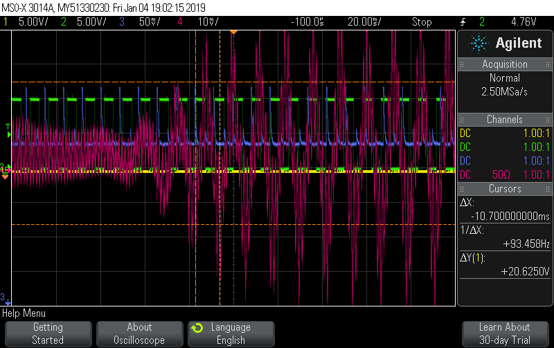
Here is a screenshot from of oscilloscope showing the behavior of the current when it suddenly cuts down in frequency.

The green trace is a square wave at 120 Hz (7200 cycles per minute) from a function generator. I am not doing anything with it this instance but it is a reference for 7200 rpm. The blue brace is me using a laser, photo detector, and rough area on the hard drive pallet to observe the actual rotation speed. Comparing it to the green trace it appears the controller is converting on 7200 rpm before the frequency cuts down. The pink trace is the current picked up by a current probe. (The DC offset is an artifact of the probe.)

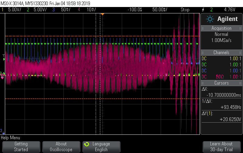
This is the same thing with a longer time scale.

Thank you

Did you also set sensorless_estimator.config.pm_flux_linkage ?
Did you find the sensorless section in the docs? https://docs.odriverobotics.com/commands.html#setting-up-sensorless

This is how I resolved and will continue to try to resolve this. I never managed to get the sensor less estimator to return useful velocity estimates, but I did manage to get the sensorless spin up to successfully spin the motor up to 5000 rpm with an acceleration so slow it took several minutes to spin up. That was okay, since this this is supposed to just run continuously. I could not get it to hold 7200 rpm like I would like with a safe current for the motor, but it would do. I then modified the firmware such that the in sensor less control, the controller never left the spin up routine and just ran at constant velocity in open loop.

The goal was to synchronize the hard drive pallet with an external reference pulse. To do so, I hard calculated the phase of the current, using constant amplitude, based off the reference pulse and one of the hardware timer counters, after I got the it to spin up to 5000 rpm. The width of the variation in timing between a point on the rotor and the external reference was 11 us on a good day and 15 us on a bad day. That can be thought of as +/- 7.5 us and is 0.125 % of one rotation.

The plan from here is to try to reduce the timing error and the current being put through the motor using a custom encoder.

To the creator, yes and yes.