Project Drumline Robot

As I mentioned in another post, I am building a drum-playing robot. Specifically, I’m making a robot that plays the drums that typically accompany a modern marching band: snare drum, tenors (quad-toms), 4-5 bass drums and cymbals. Eventually, I hope to pull the whole thing on a bike trailer.

One of the main things that will differentiate my robot from some of the exisiting drum-playing robots, is that I intend my robot to be LOUD—as loud as the 7-8 human players that it typically takes to play all of the marching drums. I’m starting with a single bass drum, and will add a snare drum next. I hope to have these two drums operational by the end of the summer.

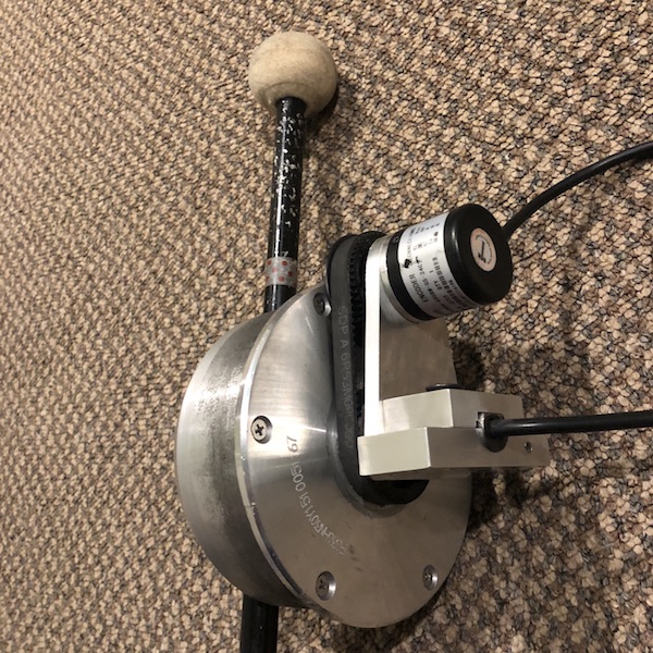
To estimate the required speed for loud playing, I recorded a video of me hitting the drum at full volume, and used a free java app to analyze the motion and measure the speed at impact.

  • The stick speed of a full-volume hit is 60 rad/s (573 RPM)
  • A quick playing tempo is 16th notes at 120 BPM
    • For the whole motion, approach and retract, 120 BPM works out to 0.5s per ¼ note or 0.125s per 1/16 note. That leaves roughly 60ms to accelerate to 60 rad/s, a constant acceleration of 1000 rad/s2
    • A super-human playing tempo is full-volume 32nd notes at 120 BPM—2000 rad/s2
  • My bass drum mallet has a moment of inertia that I calculate to be 0.0025 kg·m2

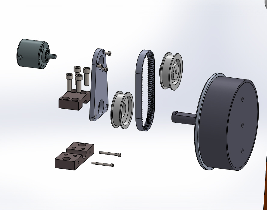
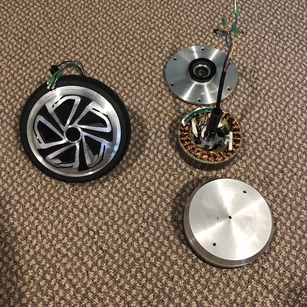
Based on these figures and the data available in the Odrive motor spreadsheet, I’m hoping that hoverboard motors will provide the performance I’m looking for.

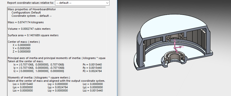
Oskar calculated the MOI of the hoverboard motor to be 0.00701 kg·m2.

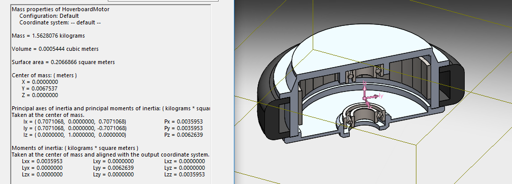
My model of the motor returns a MOI of 0.00626 kg·m2, which is consistent enough for me to rely on my model for subsequent values.

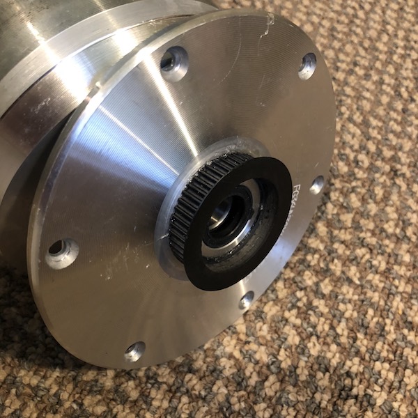
I spent some time in my father-in-law’s machine shop this weekend, and put the motor on a little bit of a diet. I removed the tire, turned off the tire flange, and faced the motor to remove the patterned top.

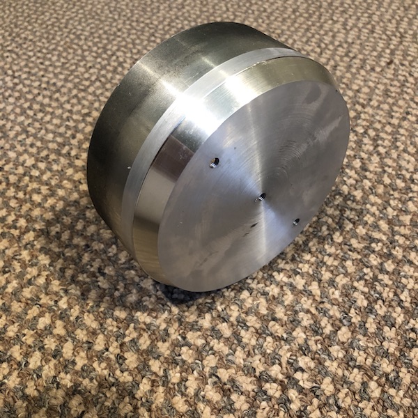
I haven’t had an opportunity to weigh the new motor, but my model calculations puts the hoverboard motor MOI at 0.0025 kg·m2.

  • At this point the combined (calculated) MOI of my actuator is Itotal = 0.005 kg·m2
  • τmax = (Itotal)( amax) = (0.005 kg·m2)(2000 rad/s2) = 10 N·m

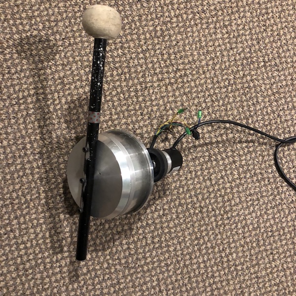
So, it looks like the hoverboard motor, as spec’d, should just barely provide me with the acceleration I need for peak performance. The next step is to test the real-world acceleration to see if it will meet my needs. If not, I can put the motor on an extreme diet, which will reduce it’s MOI by another factor of two:

1 Like

This post details my prototype/first drum motor. I already see things that I want to do differently as a produced more of these, but I want to document my progress and solicit your input and comments.

I will to provide position feedback using a conventional rotary incremental encoder ($18 Amazon).

I have designed a simple two-piece clamp to grip the center shaft of the motor and a bracket to support the encoder above.

I ordered GT3 Pulleys at a 1:1 ratio and a belt from SDP/SI using their handy center-to-center distance calculator. SDP/SI has a $30 minimum order, so I ordered two sets of pulleys and two belts. The total with shipping was $57, so nearly $30 per motor. Ouch. This brings my encoder costs per motor to about $50. More than I’d prefer, but doable.

I squared up the tapered center nub on the backside of the hoverboard motor, and turned the inside of the GT3 pulley to match with a close/press fit. Fitting nicely on the backplate of the motor, I secured the gear with epoxy.

I conventionally machined the small bracket pieces from ½" aluminum, and used the CNC to mill the encoder bracket from ¼" plate.

For now, I’m just using some 10-32 machine screws to attach the mallet to the front plate. But since these fasteners will take a (literal) beating, I suspect I might have to fabricate some clamps that grip around it’s circumference. We’ll see how long it takes to fail.

Here’s a photo with an unmodified motor, the final pieces and a second photo showing the final assembly.

The next step is to connect the motor to my ODrive and start taking some real-world data. I hope to get there tomorrow.

1 Like

The peak torque @ 75A should be around 30Nm.

That’s great news. 30 Nm is plenty for whatever I want to throw at it. I’m running from batteries so 75A should be no problem. I will probably need to vent the motors to address cooling. Do you have any experience with how hot they run, and what sort of sustained currents can be maintained? What about the Odrive— does it need to be fan cooled to deliver 75A bursts?

In your application the 75A will break something.
I guess that you will need about 30-40A for 50ms (acceleration), 0A free fall + bounce and 5-10A for holding.
The motors and ODrive can handle that without cooling.

With some coding you could get rid of the encoder and use the hall sensors for commutation and basic velocity and position control.

We actually have hall stuff working on the devel branch now. Though I think the accuracy is may be insufficient for nice trajectory tracking. But maybe a well tuned trajectory with feed-forward is sufficient for this application?

@ojibberish I’d suggest you keep the hall sensor wires intact. Then you can use your first prototype and test both hall and encoder based operation, and see if the hall one will be sufficient.