But even there, actually, it’s pretty much air-gapped.
This means that by default, the cooling of the coils will be very poor. I think in the original application there was not so much that could be done since the motors needed to be sealed against water and dirt ingression.
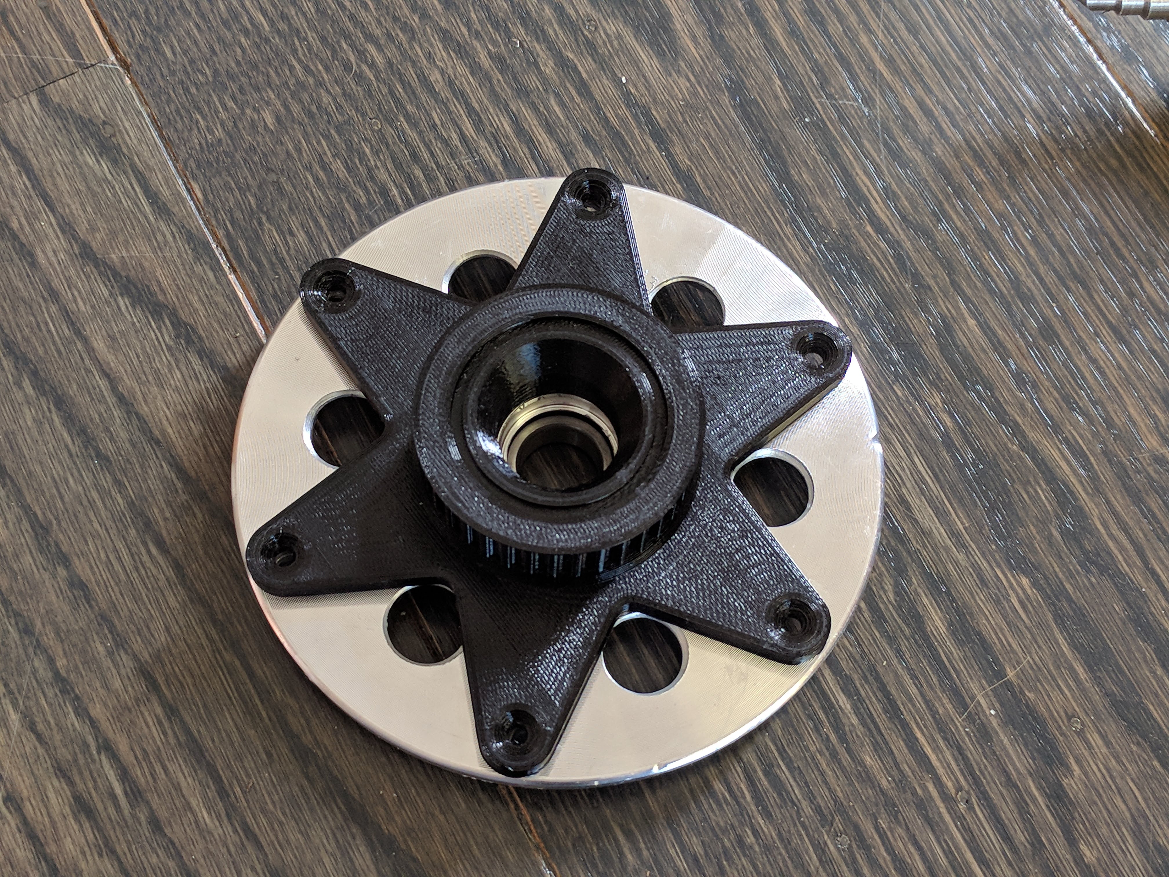
I did a test-print, and it’s starting to look less like a hoverboard wheel and more like… I don’t know what, but not a hoverboard wheel. Looks cool though.
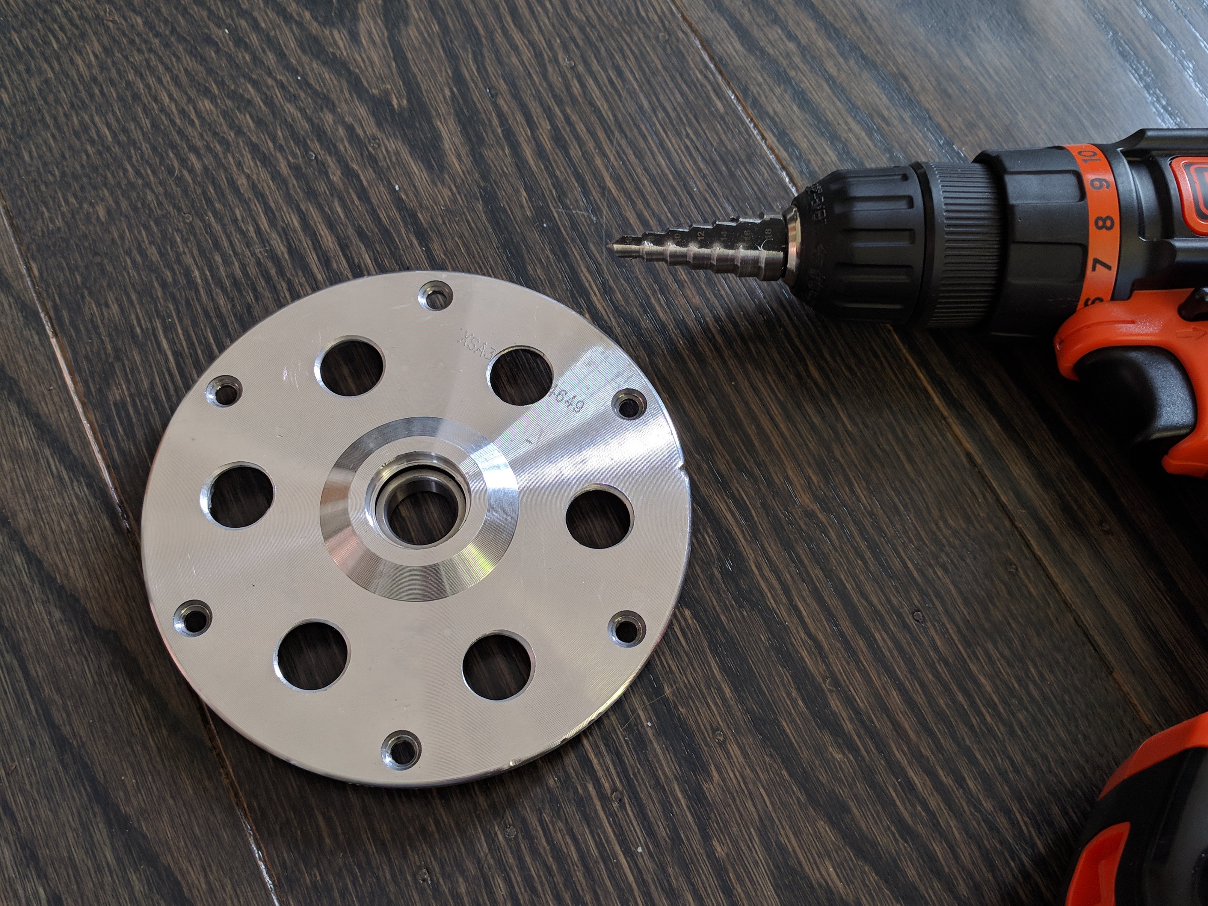
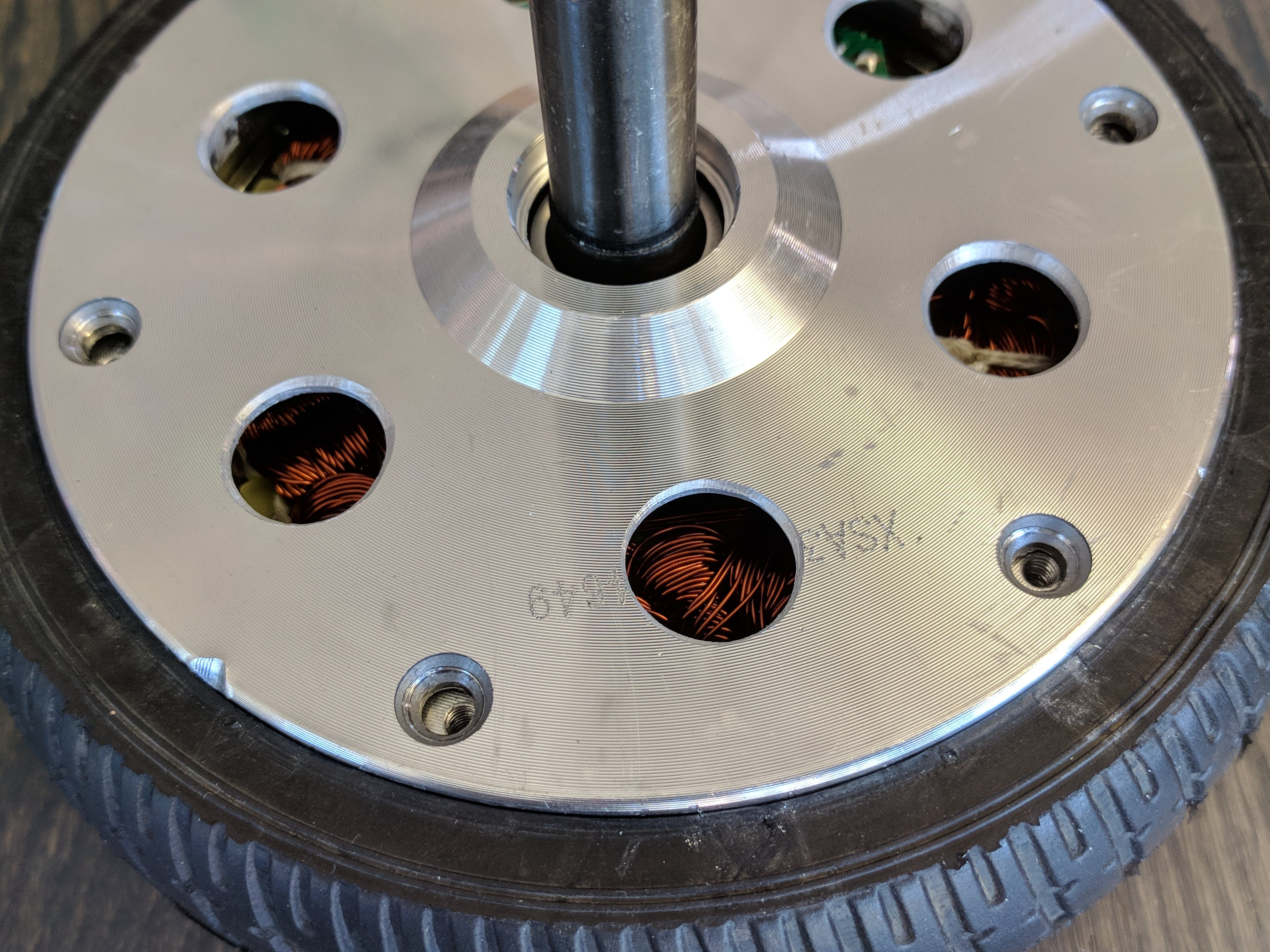
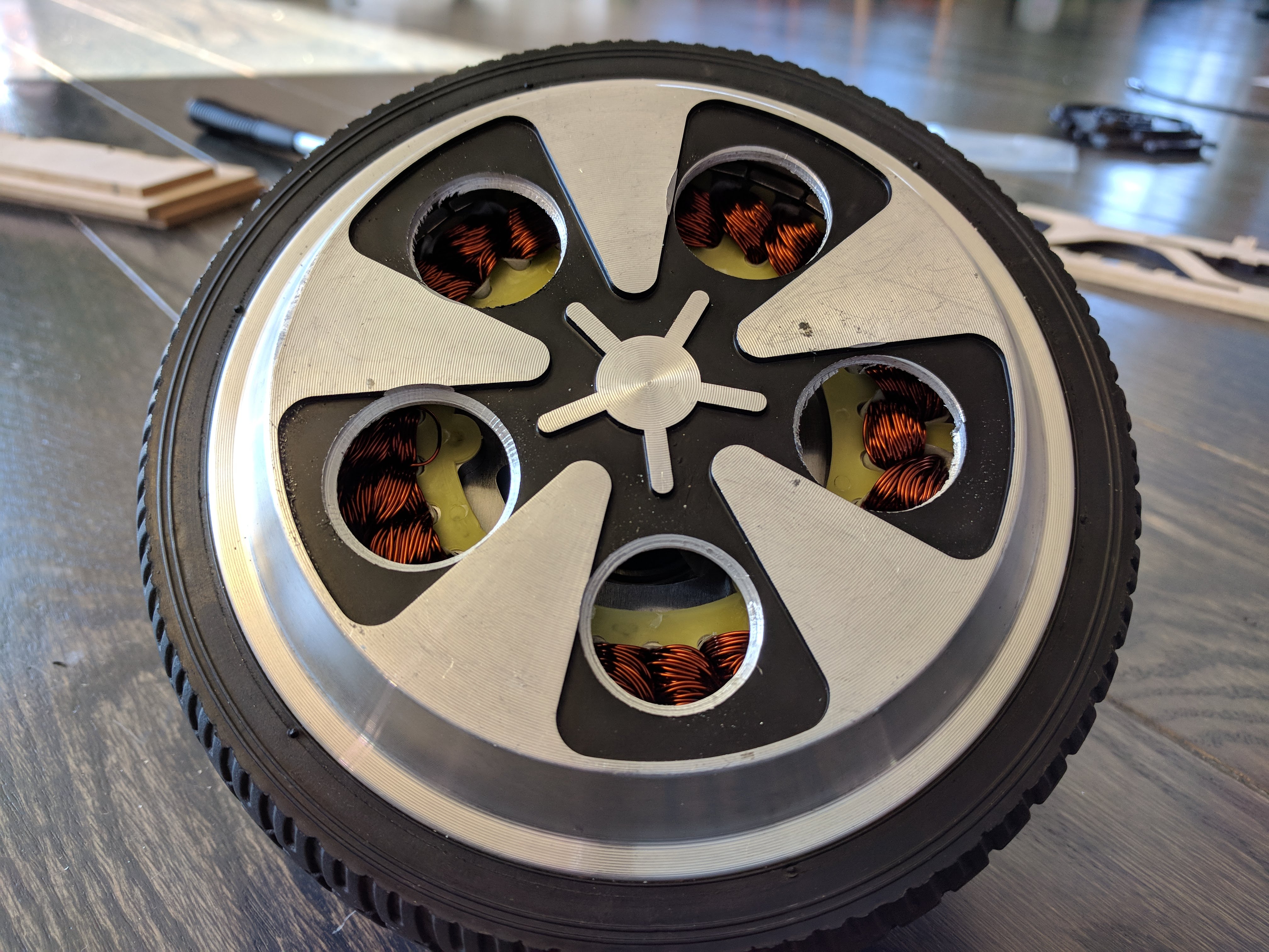
On the other side where there is no starfish, we can make big holes! Next time I would probably put them slightly further out. I doubt it makes a huge difference though.
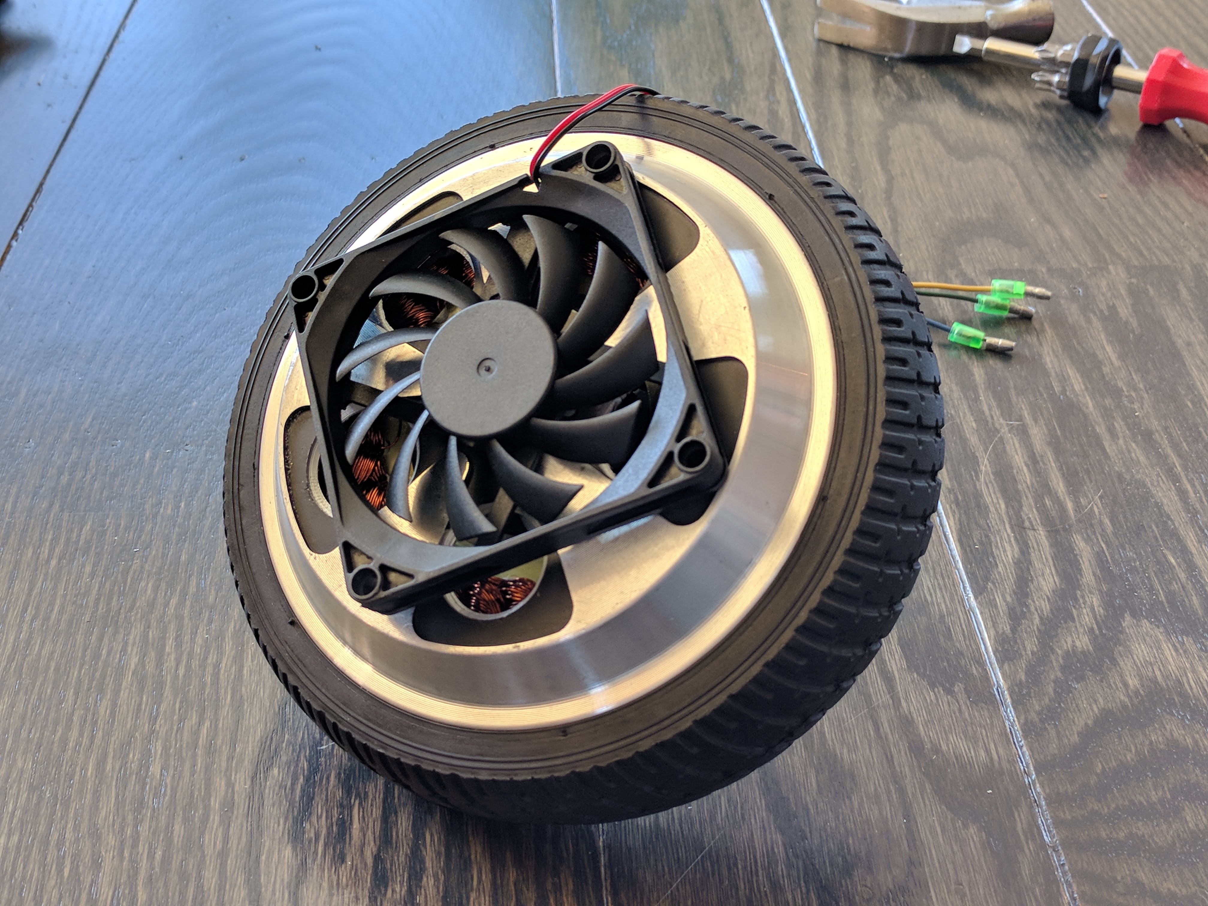
Since the wheel should only spin a couple of turns, we could even add a fan here. This fan is just for illustration, it is completely the wrong size. Not sure how I would attach one, maybe just glue it?
Hm, I think Hobbyking has an error on their spec page. Ohms law dictates that these two statements are mutually exclusive:
8.1 ohm phase-to-phase.
35A current rating.
Unless you are driving it with 210V power and dissipating 11kW of losses. Maybe they mean to write 3.5A? That would be quite high still, but more reasonable.
Yes I thought about putting the pulley on the opposite side, but that creates even more leverage. The wheel weighs a few kg, but the belt tension I will need is somewhere between 500 and 1000N.
Putting the pulley at the larger diameter of the wheel itself means I will loose some gear ratio, which is still something I want to maximise.
Hobby Kings specs seam to more for entertainment than anything else They cant get the hole spacing right in the specs, and the pictures vary within the same product… Most gimbals motors I’ve bought from them didn’t match either the pictures or the specs. Luckily, I was 3D printing/Laser cutting the mounts and the hole size and spacing was arbitrary.
If you want even more torque out of a cheap motor then take a look at the link below. I can’t say for sure that they are direct drive brushless motors but implies so by comparing them to gear motors:
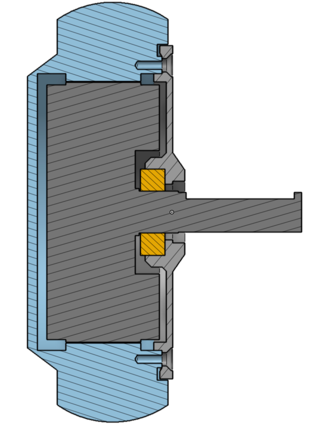
Why not drill a hole in the center of the rotor “cover”, and replace the shaft with a longer one, thus giving you double sided attachment to the structure of your robot arm?
The main reason I want to try the cantilever way is that it would mean there are less steps and easier for someone else to build.
Your suggestion is a good idea and is probably what I’ll try if the original way doesn’t work.
I’m sure motor suggestions are great and appreciated, but none of these are as cheap or powerful/low kv as hoverboard motors esp used ones. Cheap defined not only by cost but availability and limited reworking.
I think the topic is great, but I see a couple of motor suggestions that are neither as cheap or as powerful as hoverboard motors :D. I’ve been interested in repurposing a few hoverboard motors for a slightly different project (this year electric wheelbarrow for rough woody terrain, next year maybe e-chair in similar conditions) and am very intrigued by the original hoverboard motor repurposing:-)
Not trying to discourage anyone tho just noticed a couple other motor suggestions and wanted to voice that I think the original plans are very interesting to me and I think going to specialized options may have some benefits but affirming that there is distinct appeal to hoverboard motors.
I’m also tring to make robotic arm using brushless motor for electric bicycle.
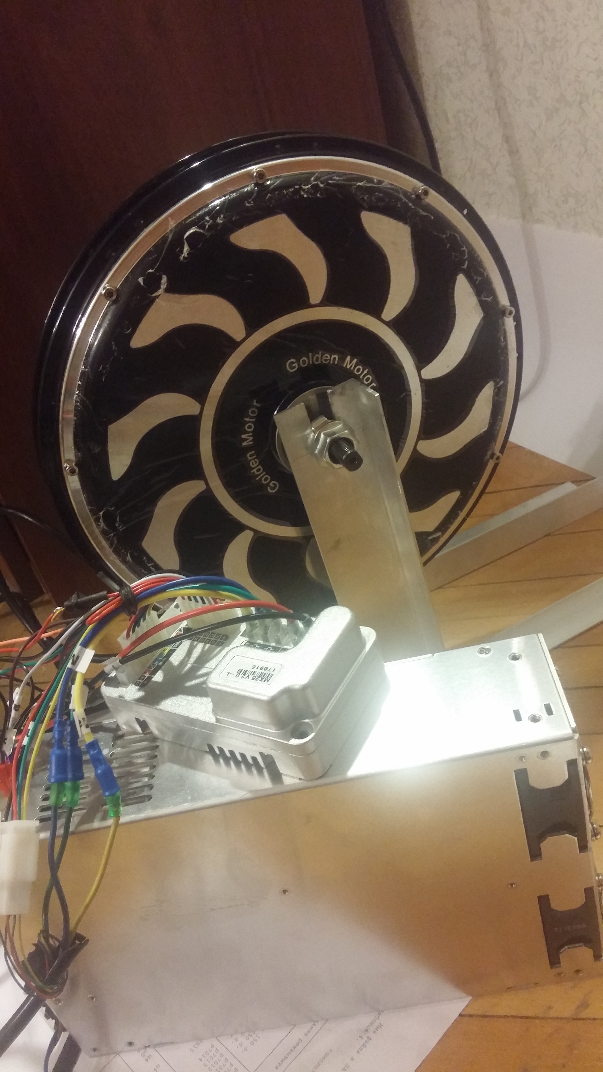
But I’m trying to do this using the motor Magic Pie 2 https://www.goldenmotor.ca/products/Magic-Pie-Edge-Wheel-Only.html
It has 70 nM torque and 1500 KW, 48 volts. The motor weighs about 10 kg.
Also i have power source MEANWELL RSP-3000-48
I tried to use native controller for electric bicycle like this https://www.goldenmotor.ca/products/BLDC-Motor-Controller-48v2000w.html to drive the motor, but i ran into some limitations.
For example, the native controller behaves strangely at very low engine rpm - It blocks the motor as if it doesn’t understand how the hall sensors are located at the moment.
Or controller turns off when the engine has some load current but rpm is zero for 2 seconds (i think this is for do not burn)
I’m very very interesting in this topic.
It would be great if the ODrive be able to control the engine of such a mass with and such current.
Native controller can not properly control the motor Magic Pie.
Can anyone know which motor from the electric bike will be accurately controlled by ODrive? Because I’m starting to think that the cause might be also in the motor
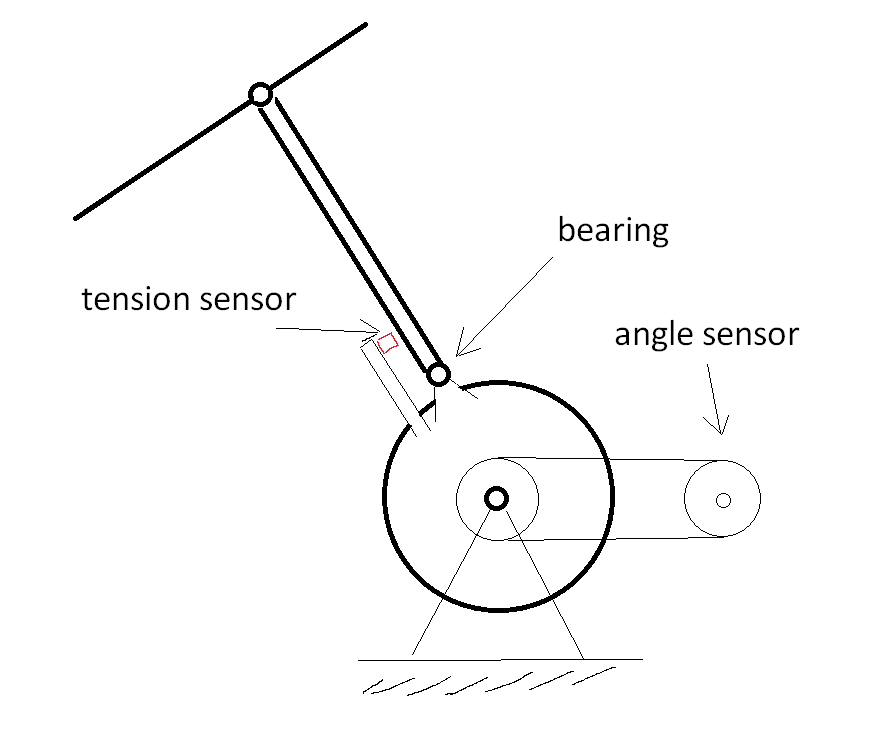
My idea of force-torque control for robotic arm that I’m trying to implement.
The idea is to add a torque or pressure sensor to the robot arm.
It is necessary to know the force applied to the arm of the robot to give an equivalent resistance to the motor. This is necessary for the arm to remain fixed when applying external forces.
Are you sure you need the tension sensor? The tension applied by the motor is proportional to the motor current. If you have a PID feedback loop controlling to a position target (either inside ODrive or running on an Arduino/RPi/etc) then your PID controller calculates the force required to keep the arm in the same position. A tension sensor might be more accurate but if I understand what you’re trying to do then I don’t think you need it.
I think in principle your setup should work: The ODrive can drive 48V motors and you have an encoder (angle sensor) included in your diagram. I agree with urdman that you probably don’t need the force sensor, the encoder (angle sensor) should be enough.
I tried to find the current rating of the motor, but I couldn’t, so I can’t say if the ODrive will be powerful enough to drive the motor to its full potential. My guess is that it should be just about enough.

 They cant get the hole spacing right in the specs, and the pictures vary within the same product… Most gimbals motors I’ve bought from them didn’t match either the pictures or the specs. Luckily, I was 3D printing/Laser cutting the mounts and the hole size and spacing was arbitrary.