Are you sure you need the tension sensor? The tension applied by the motor is proportional to the motor current. If you have a PID feedback loop controlling to a position target (either inside ODrive or running on an Arduino/RPi/etc) then your PID controller calculates the force required to keep the arm in the same position. A tension sensor might be more accurate but if I understand what you’re trying to do then I don’t think you need it.
I think in principle your setup should work: The ODrive can drive 48V motors and you have an encoder (angle sensor) included in your diagram. I agree with urdman that you probably don’t need the force sensor, the encoder (angle sensor) should be enough.
I tried to find the current rating of the motor, but I couldn’t, so I can’t say if the ODrive will be powerful enough to drive the motor to its full potential. My guess is that it should be just about enough.
Ok, thanks
Then i will try to do it and send the results.
Yesterday i send a request for an order ODrive but have not received a reply yet
I read the ODrive documentation. So, about the Encoder 600 P / R order and the power resistor everything is clear (although I was planning to use a simple angle sensor like this aliexpress.com/item/Full-Circle-No-Dead-Angle-12-Bit-Holzer-Angle-Sensor-0-360-Degree-0-5V-Output/32422949989.html and connect it to Adruino).
I consulted with the seller of the Magic Pie motors https://goldenmotor.ru and I have a couple of questions:
-
Are MOSFET’s powerful enough to be used in Odrive?
The current consumption by the Magic Pie motor reaches 60A and I’m planning on using the odrive to
hold a static load.
The seller proposes to use the MOSFET IRFB3077 https://aliexpress.com/item/Free-shipping-10pcs-lot-IRFB3077-TO-220-75A-210A-new-original/32688466241.html
May I solder these MOSFET’s in the Odrive circuit board instead of the existing ones or is it not necessary? -
The Getting Started Guide shows how to connect motors without Hall Sensors to ODrive.
But the Magic Pie motor has built-in Hall Sensors.
What is better to use the Encoder 600 P / R without Hall Sensors or connect Magnet Encorder
paired with the Hall Sensors of the motor?
And if so, is the AS5311 suitable for this? And how connect it to Odrive then?
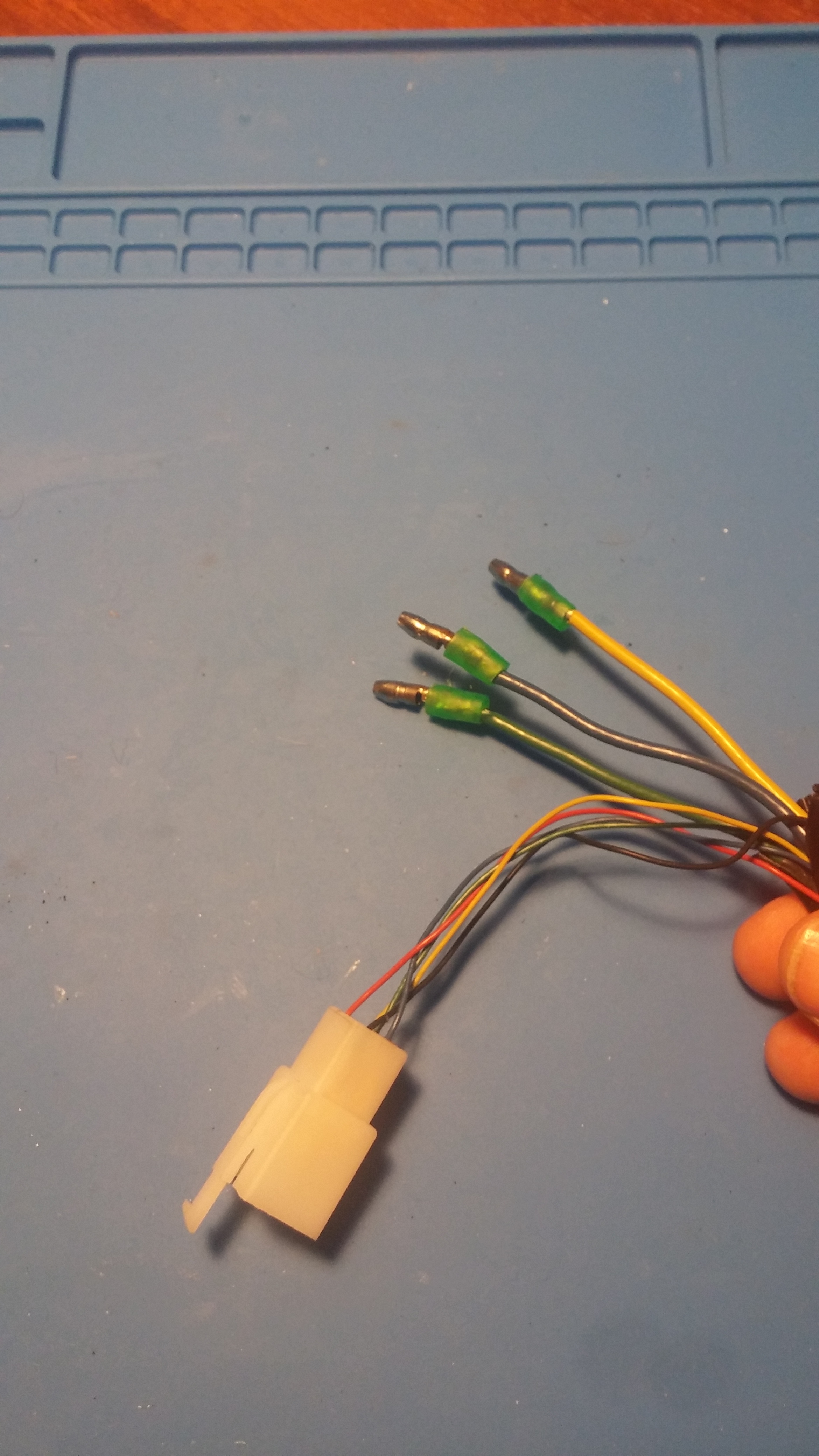
From the Magic pie motor there are 3 power wires
Another 3 wires from the Hall sensors
And 2 wires of the Hall sensors power supply
Yes the MOSFETs should be enough to drive a motor rated 60A, but if you plan to do so continously you should use a heatsink on the MOSFETs and add a fan for forced air cooling. Please see the second half of this post for data on cooling of the ODrive.
We plan to support Hall inputs in the future, but we do not support it now. However if you use an encoder you do not need hall inputs, because the encoder tells you all the information that hall sensors would tell you but better. So you can use encoder without the hall signals. The 600 P/R encoder is easy to mount mechanically; the AS5311 and magnet ring is much higher resolution, but you need to align the sensor board well with the ring. Also the AS5311 makes it very complicated to use the index pulse, so you can’t rely on that for now (not using index should be fine for basic calibration every startup, if you can start without load).
Any early feedback on how much weight this arm will be able to lift? I’m also curious what the duty cycle might look like. If it’s over 25kg I’m pretty much going to be ecstatic.
I’ve been doing some VERY homebrew experiments and iIt turns out that using your arm to emulate a command stream based on visual odometry / slam is quite tiring and an error prone process. So I hope you will kickstart this project sooner ratther than later. I can promise a linkedin post about it from me.
and me, i wont just post about it on linkedin… i simply can’t wait to build it myself !
I do not need such 25Kg load. 5 or better 10Kg, with somewhere between 750mm to 130mm reach would be awesome 
Very cool… Do you have a link to specs? IE inner outer diameter of the magnet ring…
Cool, the have some magnet rings in the 40mm range… more than large enough for a gimbal motor… How touchy is the alignment between sensor and ring?
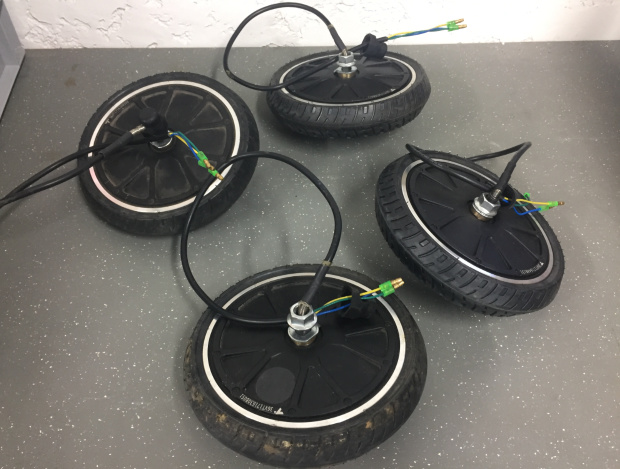
I have not read all posts yet. but check what a colleague of mine sent me from the trash: 4 hoverboard wheels, supposedly they all work.
I guess it’s a wonderfull excuse to buy a pair of 48V odrive boards. or should I buy 24v instead? How can i figure it out? (i should know the rate voltage of the original batteries soon)
I plan to dismantle one in about 10 days, just to document and count the magnet pairs.
I also need to find and understand those magnetic ring encoders…
If you intend to gear it appropriately, 48V should be fine. The hoverboard motors run around 8-12mph topspeed at typically 36V (you should check! I am not sure about this number, quite approximate).
Chances are the max RPM of these motors is not super high at their 36V running speed, so that’s why if you gear it appropriately you’ll have higher continuous power at 48V drive than 24V drive (think 2X rpm with 1/2 current vs 1X RPM *1X current).
There are reasons to make the drive 24V, like maybe you don’t want them to spin too fast or you’re worried about losses at higher RPM and 24V has plenty of power for you.
1 Like
ok. thanks for the feedback. it’s clearer for me. Bottom line is I should buy one 48V, at least for the sake of checking the RPM under 48V.
Assuming I use those for an indoor vehicule (i have not decided if they’ll go to a hoverarm or a vehicule yet), how i possibly gear those motors? the wheel is part of the motor itself. i’m a bit confused
Decide your project, choose drive second :p. I assumed you were planning on an arm like in this project.
A lot depends on your project. 24V would work better for any case that you’re spinning it mostly at slower speeds (if 50% throttle at 48V is worse for motor efficiency than 100% at 24V if there is any ripple in the current)
Hello all.
Just a warning. The magnetic encoder rig are very brittle. To not drop them or press to hard on them.
Broke already one when I dropped it.
1 Like
@G_Penzo
please send pictures/video about you do the mounting & alignment of that magnetic ring with its encoder because it’s pretty obscure to me.
Can I use an inductive sensor or something similar with the AS5311 and magnet ring as an external index signal? Or does the index signal need to be exact on a incremental pulse?
In principle you can use an inductive “home switch” in parallel with the encoder index, to form sort of a 2-stage indexing. We don’t have code for this yet though.
That said, if you don’t require the full repeatability of 16-bit, you could probably just use the external sensor as an index.