Decide your project, choose drive second :p. I assumed you were planning on an arm like in this project.
A lot depends on your project. 24V would work better for any case that you’re spinning it mostly at slower speeds (if 50% throttle at 48V is worse for motor efficiency than 100% at 24V if there is any ripple in the current)
Can I use an inductive sensor or something similar with the AS5311 and magnet ring as an external index signal? Or does the index signal need to be exact on a incremental pulse?
In principle you can use an inductive “home switch” in parallel with the encoder index, to form sort of a 2-stage indexing. We don’t have code for this yet though.
That said, if you don’t require the full repeatability of 16-bit, you could probably just use the external sensor as an index.
I ran a hoverboard motor from 2x6s lipo in series for just a smidge over 50v and got a top speed of 16mph, average 13mph on some slight gradients. Stall conditions under braking while powered were 15A, about 740 watts.
That was what I was thinking. The AS5311 gives an index pulse for every pole pair, so we can’t use it for now. So if I only use the incremental part of the AS5311 and a separate index pulse from a inductive/hall sensor, it will only need to find the index on each startup after first calibration? I want as little movement on each startup as possible, and the motor position will not be maintained when it’s off!
Would it be possible to use one of the built in hall sensors in the hoverboard motors as index for the encoder? It’s a 27 stator pole motor. What if I treat it as a 3 pole motor, and use the rising edge of one hall sensor as index. And devide the pulses from the AS5311 by 9. I might not get perfect position control this way. But all I want is to run the motor as slowly as possible, and with as little start-up movement as possible.
Hm this gets messy because the rising edge of that signal is at a different place depending on which direction you come from. Maybe you can work around this by rotating one way, and only “arm” sensitivity to the index edge after half an electrical turn or something. This means you should get a consistent side of the pulse’s width.
I’m just trying to look for a solution, without being an expert.
I’m still thinking that this might be a solution.
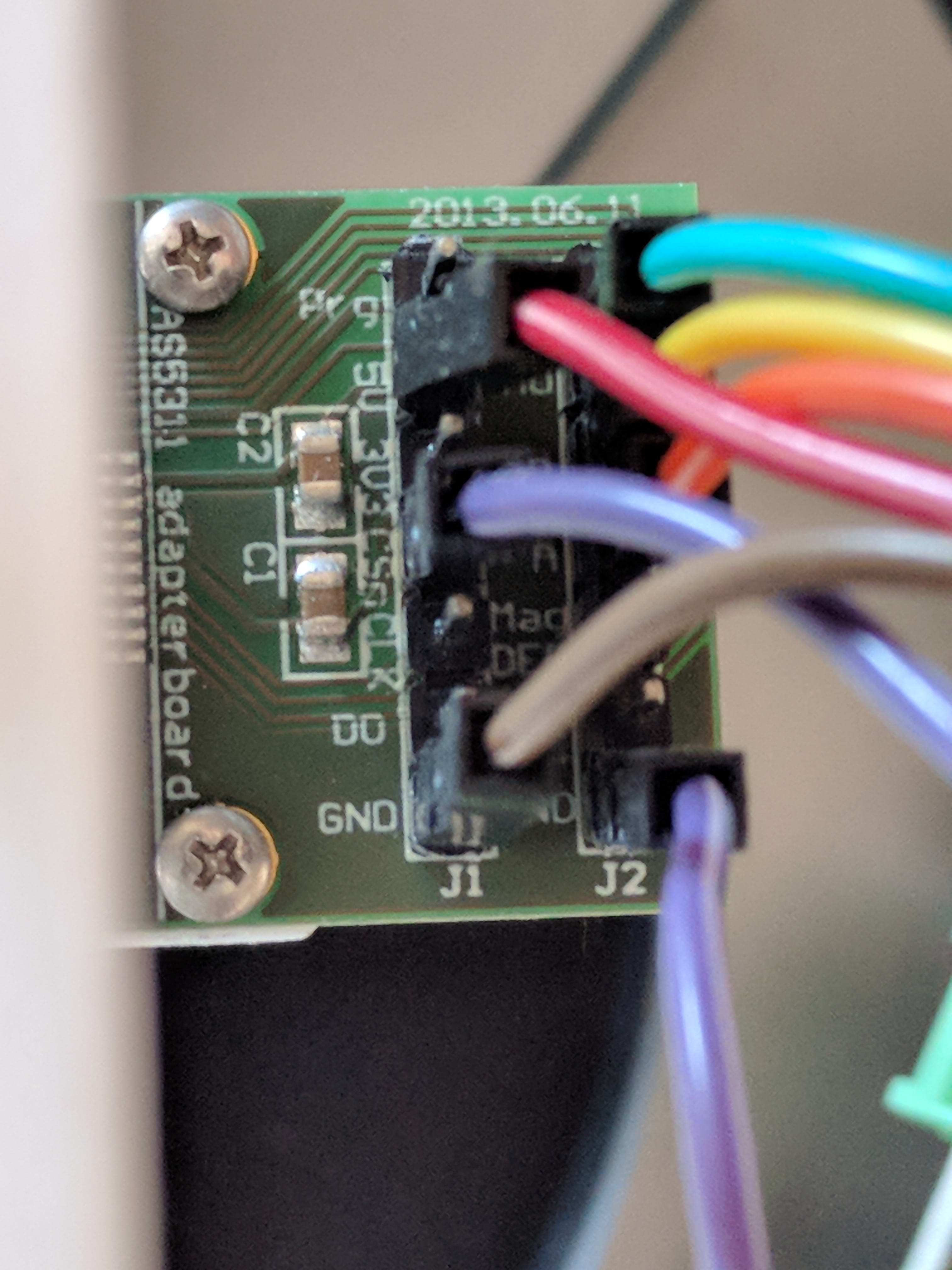
The magnetic ring and the AS5311 fits inside the motor with just two 3D printed brackets. See photo. No modifications to the motor needed. At least as long as you don’t need cooling.
Also AMS claims that the AS5311/ring combo is immune to external magnetic stray fields. (I guess that means it will not be affected from the stator poles being close?)
Vdd and Vss can be taken from the hall sensor PCB. and wires from two hall sensor can be used to connect to the incremental pins on AS5311. The last wire remain on a hall sensor. No extra wires needed.
Use rising edge on hall sensor when the motor is spinning in one direction and falling when it’s spinning in the other direction.
The number of pulses from the AS5311 between each hall sensor edge is known.
Even though the number of pulses between each index is not a hole number, and each pole is not a perfectly equal magnetically, it should not matter for a EV built.
9709.037 pulses between each of the 27 poles from my calculation.
When I write stator poles, I mean coils. I see I forgot to add stator one time.
I was hoping this forum could help me finding a solution to finish my project. When I started I thought it would be easy to find a driver for the hoverboard motor. But since my nephew is very young, I need it to drive very slowly, and that seems to be a problem. I have no space for an external encoder. Also, I can’t have the motor rotating too much at startup.
If you don’t think I’ll be able to use odrive, I’ll start looking for another solution.
Maybe ditch hoverboard motors and instead use geared motors.
Did any one of you had success using the as5311.
After trying 2 chips from ams and two chips from mouser. I still cannot get the chip to work.
When stationary and looking at the pwm signal it looks good.
When moving the motor a bit by hand I see the pwm duty changing. So the chip works.
While looking at pin A and B I get allot of garbage.
Based on documentation they implemented Incremental Output Hysteresis.
But what I’m seeing on my scope looks like the sensor thinks the motor is moving, vibrating. The motor is not connected to the odrive it is stationary.
So anyone succeed with this sensor.
I’m thinking to drop this sensor and use a traditional encoder connected with a timming belt.
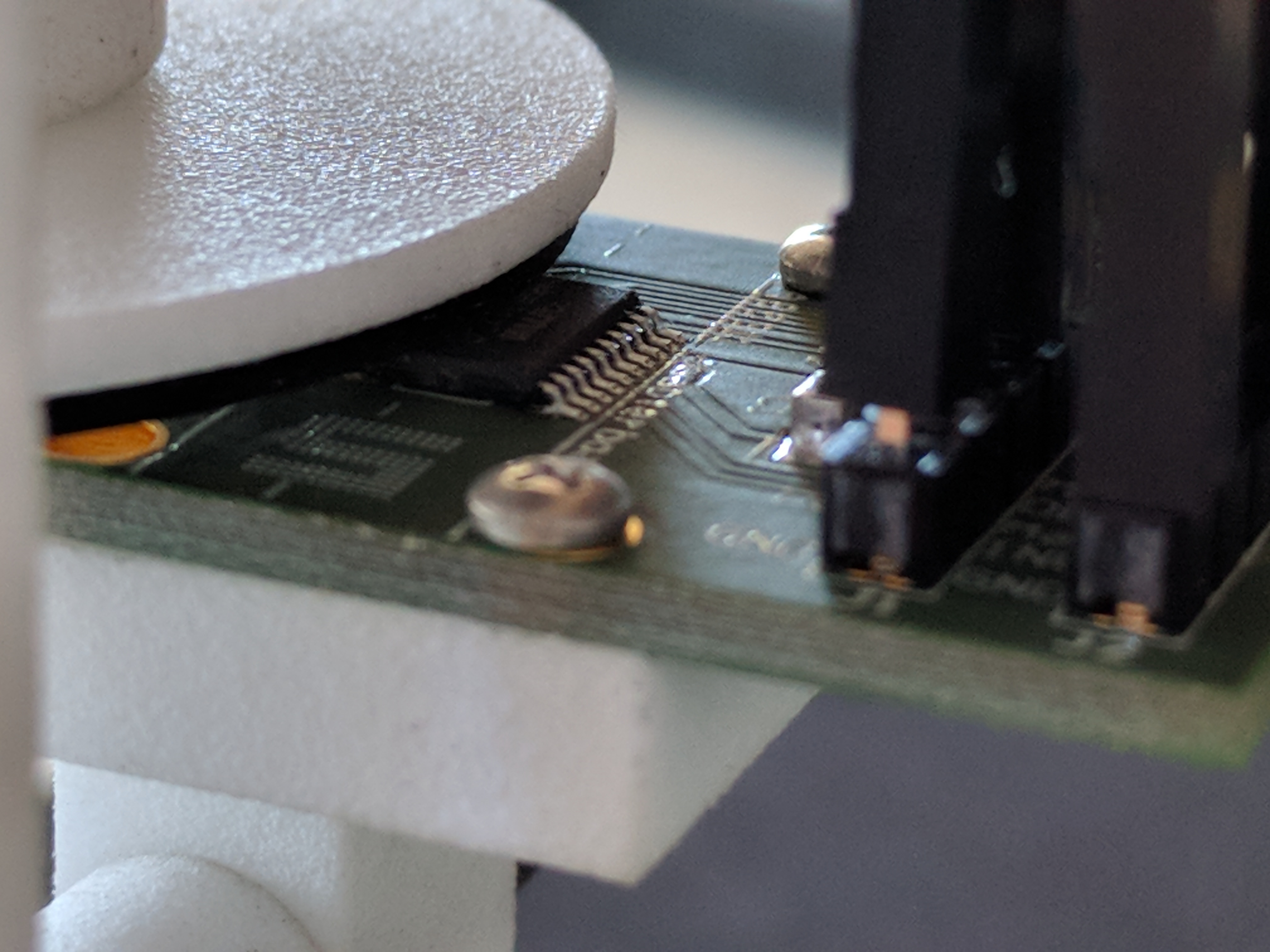
Once I got it working it was working very well for me. I used this breakout board from mouser. There are two things that I didn’t find obvious that I can share.
The sensor center is not in the center of the package, is slightly off to one side. You can see this in the datasheet, and the dotted line on the breakout board.
Problem solved, on my board I connected prog pin to gnd. Also mention in manual. And it worked.
Also I notice the further you go from the sensor with the magnet the more movement is detected by the sensor.
I notice with my hovermotor there is a bit of play. The axle can move in and out by 1-2 mm.
Can only be noticed when you pull on it. The magnets is holding it back.
I’m going to test it else I still have the timing belt solution as a backup if this does not work.
I think we will make hall effect encoder input available within 1 month, so then you should be able to use ODrive directly.
Are there any news related to the implementation of the hall effect sensors?
For a 30 pole motor we would get 90 state changes per rotation if the hall sensors were used as three phase digital encoders. However this would allow only for a very coarse slow speed commutation (4 mechanical degrees per step, or 0.9 cm on the circumference of 10" wheel). I doubt this is how it is done in the hoverboard since it balances very well.
Could the hall sensors be instead sampled as analog values and used the same way as back-emf values to calculate the rotor position? I think this is how it is done in the hoverboard since there is nothing else attached to the motor/wheel that could act as an encoder.
We have been discussing recently (again) with some friends the benefits of all of us having the same motors and drives on our robots so this topic has arisen again. The slow speed performance is important for differential wheeled robot when trying to point itself in a certain direction. I guess, from reading this forum, there might be more people interested in making these motors work with odrive and without an external encoder.
TL:DR - It will work fine at low speeds. If you are REALLY needing fine position control you will need an encoder.
I am not an expert on controlling a BLDC via Hall sensors. However I have implemented Field Oriented Control with BLDCs. The method you suggest is basically how magnetic encoders work with a diametric magnet that senses the orientation of the magnetic field to get an absolute position. But I will say that I am fairly certain that the hoverboard does use the simple method of commutation by just watching for the hall transition pulses across the poles. It’s enough to handle the startup torque at low speed. In general with the hoverboard you can safely assume whatever the simplest way possible for the most part is what they use… I think @madcowswe idea is to make it consistent with the way the rotary encoder and using some velocity to estimate position of the motor to gain back some of this “lost” information.
Yes, we just finished a demo using it, you can expect it to come out with firmware v0.4.0 or v0.4.1. The 90 states per rev makes for quite smooth velocity control, and decent enough for basic odometry.
Actually the signals are digital halls in the hoverboards, but you are also correct that it’s not used for the self-balancing. They use gyro sensors as primary feedback, the hall’s aren’t used in the control loop, just for commutating the motor. The primary control loop just demands votlages or currents (not sure which one) in the motor directly.