I am not the first person to decide to use the ODrive boards to make a Robotic Quadruped, and I am sure I wont be the last. However, what may be interesting to those reading this is that I plan to document as many steps as a can for how I’m making the robot through (hopefully) well edited videos.
Throughout these videos, I will be trying to educated viewers on different concepts and why I decide to do certain things as I stumble my way through creating this thing.
This is a work in progress and I have already started posting up some videos. If interested, I have linked a playlist below:
Something that may also be interesting for those using Hoverboard motors…I give a breakdown for how/why the Hoverboard motors actually have 90 states per revolution in this video:
I plan to post many more updates as the system evolves!
I’m trying to make these videos be beneficial for as many people as possible, so please feel free to give me feedback if you see something wrong, or if you think I am going about something incorrectly.
Just to say, I think this is brilliant and I’m finding it really useful to get your detail and reasoning.
I’ve watched the three vids you’ve done so far and looking forward to seeing the rest.
I was actually looking for a high-torque low-cost motor for a different project, and had picked one that was both weaker and more expensive than the Hoverboard motors you’re using. So it was really useful for me that you chose to stop and talk about them!
Do you know if you can buy those motors just as motors (ie, without the wheel attached, with different shaft options, potentially for sale in large numbers, etc) or are they just replacement parts for the Hoverboard and that’s it?
Hey @jbombastor, glad you like the content! I wasn’t able to find the Hoverboard motors without the wheel or with any customizable features unfortunately, which I guess somewhat makes sense since they aren’t manufactured with much else in mind beyond using them for Hoverboards. Buying without the wheel would have been nice though because removing the wheel of the motor was a huge pain.
I do plan on 3D printing some adapters as prototypes for mounting the absolute encoders on the motor shaft, as well as fixing the shaft to the frame in some way. I’ll eventually migrate to CNCing most, if not all, things out of metal though since its much more durable. Ill be posting the STL files up when I get to that point if anyone else wants to make the adapters/fixtures themselves.
I noticed in your ‘electrical 1’ video, you said that a motor would be located on the knee. I think that moving the motor up to the hip would be best so that inertia can be kept to a minimum. It’s similar to what MIT did with their cheetah robot. If you scroll down a bit you can see how the knee joint works. Though I’d use a capstan instead of a belt/pulley, it’s cheaper/more torque and no backlash. Also use UHMWPE rope if you decide to go with a capstan.
@HighGuise I totally agree. I have been looking at different designs for how to shift that actuator up in the leg. MIT way looks like a good candidate, I’ll check out your suggestion on the capstan alternative.
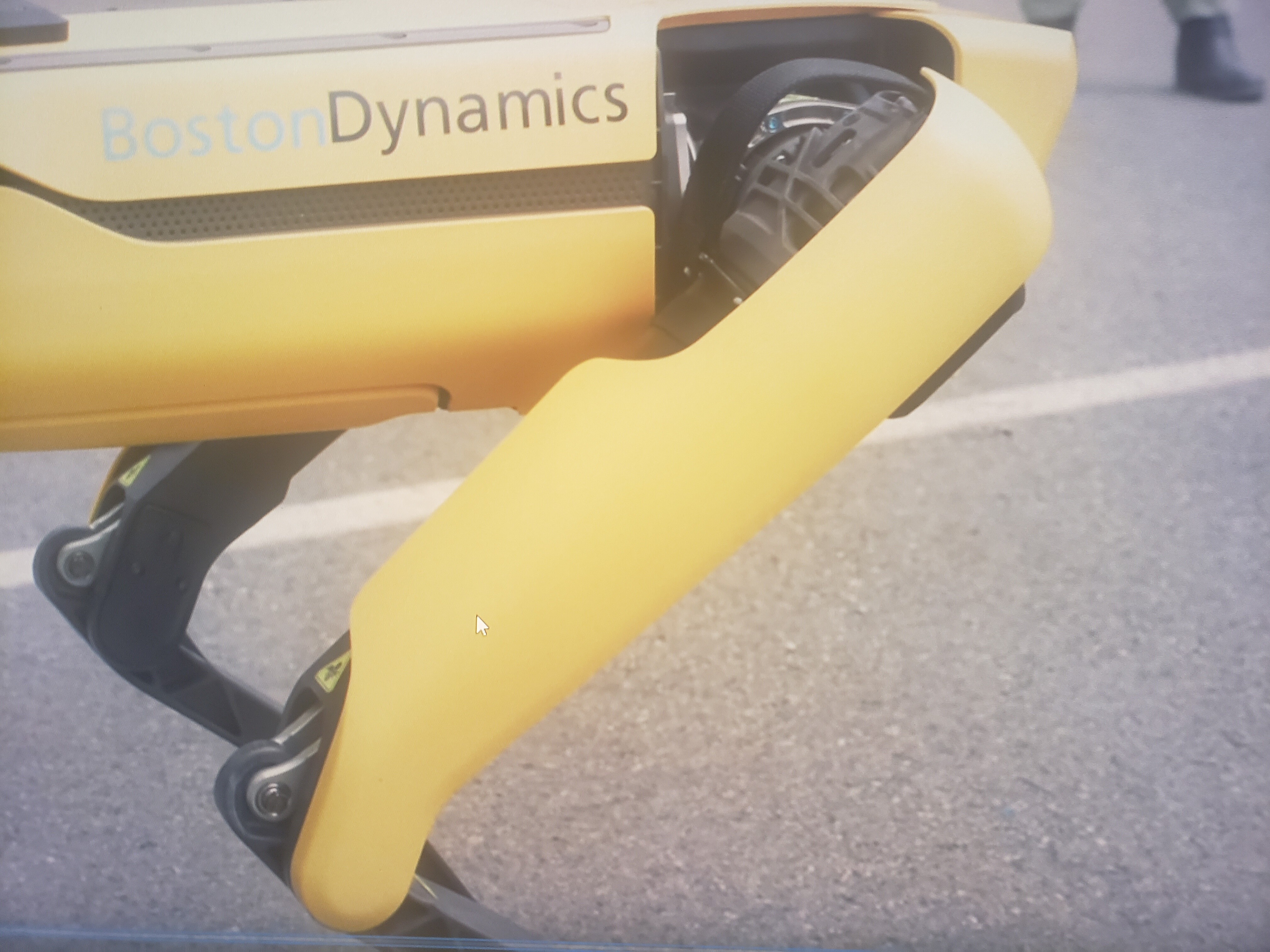
I’ve recently been looking how how Boston Dynamics tackled this and it seems like they have some form of linear actuator at the shoulder for the knee joint. With all the actuators being packed around the shoulder, I’ll really have to be mindful about space moving forward. I’d be happy to hear any other thoughts/concerns you have for implementing something like this.
I remember looking at a patent of their’s showing how it work. It’s a motor with a thread/ball screw that extends through the thigh. Then there’s a member with bearings at each end (one side connected to the ball screw’s nut and other to the end of the ‘calf bone’, you can see that end in the picture you sent).
The problem with implementing this is that it was designed for a long motor. The leg would be massive if you tried to do that with a radially large motor like the hoverboard motor. On the other hand, the MIT cheetah’s configuration is more optimised for a radially large motor. I’d spring for the MIT configuration.
CADing hoverboard motor and shoulder joint adapter with Fusion 360. I don’t usually do these podcast style videos but thought it may be interesting to some while I CAD some stuff for the RoboDog in the background.


")
