Rough running skateboard motor

Hi all, total newb here. Just hooked up an ODS1 to a Flipsky 7070 v2 110kv. This motor has 7 pole pairs and I seem to have gotten the wiring correct and the motor passes calibration without errors. Running it off of a 24v 600W Meanwell power supply.

But, it runs pretty rough, at low speeds there’s significant cogging and at higher speeds there’s a pretty loud rumble that I guess is also cogging? It’s a bit strange in that the cogging feels like a “heart beat” i.e. as it’s rotating there’s a duh-duh … duh-duh … almost like just two of the poles are binding or something. I’m running this with basically no load at this time, it’s spinning a little fan to have something to look at.

Per the docs, I messed around with the vel_gain and vel_integrator_gain and it’s not clear there were any better settings than the defaults, although there are definitely worse settings :slight_smile:

I noticed that there is an “experimental” anti-cogging routine but it’s not clear if I can run that from the web gui, is that possible or do I need to go for the local python app? It was listed as experimental at least several years ago, has this been improved at all or even is it already included in the calibration? Have people had good luck with this and a similar type of high current motor?

Is this just an unsuitable motor and I get a pancake one instead? I was hoping that this thing would be virtually silent, but that’s definitely not the case. I’m building an audio device that will run inside of the house during quiet times, so really want to do whatever necessary to get smooth velocity control with reasonable torque and RPMs around 2000.

Thanks for any insight or pointers.

B

Hi!

But, it runs pretty rough, at low speeds there’s significant cogging and at higher speeds there’s a pretty loud rumble that I guess is also cogging? It’s a bit strange in that the cogging feels like a “heart beat” i.e. as it’s rotating there’s a duh-duh … duh-duh … almost like just two of the poles are binding or something. I’m running this with basically no load at this time, it’s spinning a little fan to have something to look at.

I’m assuming you’re only using hall sensors? Those are super low resolution, and makes velocity control very very difficult, since the ODrive is essentially unable to actually measure the velocity when the motor’s between hall states – so I wouldn’t expect any sort of good control under a hundred RPM or so. For comparison, hall sensors have six states per pole pair * seven pole pairs = effectively 42 CPR (encoder counts per revolution). I would consider a “fairly low resolution but usable” encoder to be 500-1000 CPR.

Typically, the higher the encoder resolution, the smoother the velocity and position control can be. I’d strongly recommend sticking on an external encoder if you need good low-speed position/velocity control.

higher speeds there’s a pretty loud rumble that I guess is also cogging?

Possibly. Could also be some issue in the hall calibration (when the ODrive spins the motor for a minute or so during calibration). In the GUI, I’d recommend cranking up the lock-in spin current (on the motor config page) – this way, the motor’s cogging torque has less of an effect on the calibration. Usually I say to do this around 75% of the motor’s max continuous current – the Flipsky says 70A continuous, so that would be about 50-55A – that’ll get the S1 a bit hot, make sure it’s attached to the heatspreader plate and not just sitting bare on your desk.

I noticed that there is an “experimental” anti-cogging routine but it’s not clear if I can run that from the web gui, is that possible or do I need to go for the local python app?

The web GUI inspector tab has full coverage / identical functionality to the stuff you can do in ODrivetool, you just gotta search for the parameters you want to read/edit.

Note though that anticogging won’t work if you’re only using hall sensors – you need some sort of other encoder (either absolute encoder, or incremental with an index line).

It was listed as experimental at least several years ago, has this been improved at all or even is it already included in the calibration?

“Experimental” just means that (A) it’s not included in our automated firmware testing, and (B) our docs for it kinda suck :slight_smile: we have plenty of customers using anticogging in production applications.

It’s not included in the calibration both because (A) it relies on good/stable velocity gain tuning (and there’s another parameter or two you may have to tune, depending on the motor), and (B) anticogging calibration takes six minutes :sweat_smile:

Have people had good luck with this and a similar type of high current motor?

Absolutely! It’ll work on everything from a giant traction motor to a small gimbal motor.

Is this just an unsuitable motor and I get a pancake one instead?

Nope! Put an encoder on it though. The simplest thing would be to just use the S1’s onboard encoder or an OA1 (since the motor doesn’t have a backshaft that makes it easy to attach a through-bore encoder like this one). If you go for a magnetic encoder (like the S1’s onboard or the OA1), make sure to give this a thorough read first: Designing for Magnetic Encoders — ODrive Documentation 0.6.11 documentation

I was hoping that this thing would be virtually silent

That is a harder question. It’ll be a whole lot quieter with an actual encoder on it, but this sort of outrunner motor will never be purely silent – mostly just because the rotor will disturb ambient air and cause sound that way.

smooth velocity control with reasonable torque and RPMs around 2000

This is also a very very interesting question!

  1. How much torque do you need?
  2. How precise and smooth does the velocity control need to be? Like, are you building a record player?

Hey, thanks so much for the information, I appreciate the help. I do have an encoder. I bought the AS5047P, a 14 bit model, but thought since the motor is sensored I could try that out first, simpler mounting etc. FYI I also just went ahead yesterday and ordered the O-Drive 100kv motor that I can just mount to my S1 (already have the plate). Most convenient will be to mount the driver to the motor with encoder if that motor turns out to work.

Regarding the tuning though, the instructions just say tweak this up until you get vibration and then turn it back to half of that. I pretty much have vibration the whole time, it just gets worse with each adjustment up, so unclear what to do there. Also, the instructions don’t say anything about what RPM to be making those adjustments, so I was running somewhat slowly to be “safe” but later found that of course it runs more smoothly when it’s running faster. In that mode, the adjustments make no difference until the thing suddently vibrates catastrophically and kicks off. If I set it to half of that it is super rough at lower speeds so? Are the adjustments supposed to be made without the motor spinning? The instructions are simple but not really clear in that respect.

Thanks for your suggestion to up the lock in spin current - the power supply has a max of 27 amps I think I upped it to 24 but pretty much the same behavior as above.

Regarding the noise level, perhaps this is something you know - for the same RPM, will a motor with higher kV running at lower voltage or a motor with lower kV running at higher voltage be quieter? Maybe I’m wrong in thinking to get a super low kV motor, since they may be more suited to position control for robots and such. My application only requires continuous control, I was just experimenting with position control because I thought it would be interesting, but seems it just can’t work with hall sensors. Rather than print a whole new mount I will probably just wait for the new motor and mount directly to continue testing.

Thanks again!

By the way, the application is not a turntable, it’s a rotary speaker. I’m suspecting that to get the ultimate quiet I will eventually use a belt in some way, to increase or decrease the RPM while running at a suitable speed/torque that is tuned to also be as quiet as possible. Probably somewhat of a long path to optimize those variables. I’m assuming that’s why turntables and other rotary speakers also use belts.

I bought the AS5047P, a 14 bit mode

Gotcha. Unfortunately those are actually kinda encoders (they have some weirdness with the communications protocol), but they do work.

FYI I also just went ahead yesterday and ordered the O-Drive 100kv motor that I can just mount to my S1 (already have the plate). Most convenient will be to mount the driver to the motor with encoder if that motor turns out to work.

I think that’s a much better option!

I pretty much have vibration the whole time, it just gets worse with each adjustment up, so unclear what to do there

Yeah, definitely hard with halls.

Also, the instructions don’t say anything about what RPM to be making those adjustments, so I was running somewhat slowly to be “safe” but later found that of course it runs more smoothly when it’s running faster. In that mode, the adjustments make no difference until the thing suddently vibrates catastrophically and kicks off. If I set it to half of that it is super rough at lower speeds so? Are the adjustments supposed to be made without the motor spinning? The instructions are simple but not really clear in that respect.

Usually I’ll tune at zero speed, and just perturb the motor by hand, or try setting velocity setpoints from zero to some nominal low speed and then back down to zero. That being said, with most encoders, the velocity won’t have too much effect on the stability – it’s just halls that are frustratingly low resolution. I’d imagine once you have the M8325s in hand, things will go a lot smoother.

Thanks for your suggestion to up the lock in spin current - the power supply has a max of 27 amps I think I upped it to 24 but pretty much the same behavior as above.

For the future, power supply current != motor current. See here: Things in Motion: How to select the right power source for a hobby BLDC (PMSM) motor, particularly point (1).

Regarding the noise level, perhaps this is something you know - for the same RPM, will a motor with higher kV running at lower voltage or a motor with lower kV running at higher voltage be quieter?

Definitely won’t make a difference – it’s 100% nearly dependent on motor speed and construction.

By the way, the application is not a turntable, it’s a rotary speaker.

Wow, that’s super cool! Like a Leslie speaker? Or something else?

’m suspecting that to get the ultimate quiet I will eventually use a belt in some way, to increase or decrease the RPM while running at a suitable speed/torque that is tuned to also be as quiet as possible. Probably somewhat of a long path to optimize those variables. I’m assuming that’s why turntables and other rotary speakers also use belts.

Hmm, I think that’s usually just because old motors suck, especially synchronous motors that rely on a bit of belt slippage to start up. Shouldn’t have a big issue doing it in direct drive here, but belts are always nice to just give some flexibility with packaging/mounting.

A slower motor will definitely be a quieter motor, but there’s a bunch of motor form factors and constructions super super quiet across the whole speed range.

You say you need 2000 RPM – do you have any ideas as to the power and/or torque needed? Happy to recommend a motor that may work and be quiet!

I just got the M8325s motor, excited to hook it up. But, … and I can see in the picture now it has this tiny little pin sticking out. I guess I have to now buy a shaft to screw to the body of this, and one that will allow that tiny pin to pass? What is the part I am looking for called that will accomplish this? I have a few motor coupler adapters lying around but they are “female” i.e. intended to mount onto a shaft not to BE a shaft. My current motor has a 10mm shaft so if I want to use that same coupler, I guess I need a 10mm shaft.

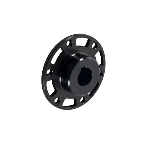
The motor’s designed for a flange mount, the pin is just for centering whatever output hub / pulley / gear / etc. You could likely 3D print a pretty decent hub to some 10mm shaft stock, something like this, maybe with a setscrew:

Right, I dont need a hole, I need a shaft :wink: with this I will need to cut and hone a 10mm shaft nub, attach this to the motor the shaft nub to this, the coupler to the shaft nub and that to my driven shaft. Messy. Is anyone aware of a flange mounted shaft? The motor should probably come with that. Not sure how anyone can use the little pin. Sure its for centering but unless you have a precision ground hole the size of this pin it wont do anything but be in the way? I did find one flanged threaded shaft but it is solid - can the little nub be ground off or otherwise easily removed? I thought I was pushing the easy button by buying this motor - I saw the pictures but just didnt look very closely. My bad.

For temporary I can just print the flange /shaft thing im looking for. But mostly what I see are like the oicture you posted - female flanged shaft adapters. Is 31mm diameter mounting holes a standard? That also sounds a bit like like unobtanium.

Right, I dont need a hole, I need a shaft

Shaft goes in the hole! Face mount outputs are pretty common for higher torque outputs in robotics, a lot of times you’d see a pulley or gear machined / printed to mount directly on the motor to bypass needing a shaft entirely, a basic example is how James Bruton does it in his video here.

Sure its for centering but unless you have a precision ground hole the size of this pin it wont do anything but be in the way?

Doesn’t need to be precise – just moreso than the screw holes – fairly trivial to drill a 3mm hole with +/- 0.25mm tolerances, but locating screw holes frequently leads to a bit looser tolerances.

can the little nub be ground off or otherwise easily removed

You can definitely hit it with a dremel, it’s just aluminum. Though I’d definitely say that if you want a shaft, just printing an adapter may be the best move – a 3D print can definitely take full torque of the motor. You could also just hand drill an off-the-shelf adapter, making a simple 3D printed insert to locate it against the centering pin.

Is 31mm diameter mounting holes a standard? That also sounds a bit like like unobtanium.

Unfortunately nothing’s too standard in this industry outside of NEMA frames – I think a lot of times people will just machine something or throw it at sendcutsend/similar.

I just wanted to post that I was able to get the anticogging setup going and it works great. Even better was the Harmonic calibration! Between these two, there’s a huge difference in the smoothness of the motor at both low and high speeds.

Wonderful to hear!