i’d like to build linear stages with good resolution. I found optical linear encoders for ~$80 at aliexpress. They are available with 1 Vpp sin/cos signal for high interpolation (up to 1000) to get down to nanometer scales. I’d like to buy such a scale and try implementing.
Project Milestones:
The most simple way to get it running is an TIDA-00178 converter board which can convert 1Vpp signals to Inkremental TTL signals. This way it should work out of the box
If this works, the ODrive ADCs can be hooked up and do what the TIDA does in Hardware in Software. The results can be compared and analysed. Hopefully the Hardware (ADC) is up to the task
An interpolation algorithm is implented that calculates a precise feedback position and
Edit: I saw that it might be hard to get hands on such a TIDA board. I think i will just use an external STM32 to calc the Incremental signals for testing. I also have a second rotary encoder on the motor shaft. the motor drives a belt that moves the linear stage with linear encoder. I’ll post some pics ASAP…as soon as my ODrive board arrives
@dlang: You have to remember that there is a difference between rotary accuracy at the motor, and end effector accuracy out in the workspace. The difference is mechanical deflection (non-stiffness), transmission backlash, etc.
@crossbreak: Thanks for sharing, I think that sounds really cool!
The 4 exposed GPIO pins do have ADC capability, and piggybacking on the current sensor trigger for periodic ADC sampling should be suitable.
@dlang: belt drive reduction is low, so you might get 80mm per rev (25mm pulley dia) which leads to so 2mm per step with 4000steps/rev, which is awful. Especially, when using CoreXY designs, transmission stiffness is an issue as it is quite low.
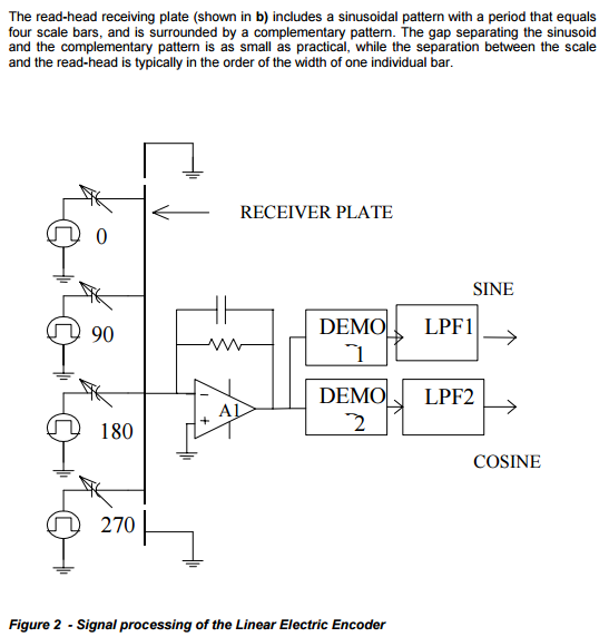
Note that analog sin/cos is a different thing than digital incremental interfacing. Have a look into the provided white paper
@madcowswe: Nice to hear that! I will try. Are there really only 4 GPIOs? I need at least 3 more for two reference switches per Axis plus the E-STOP Input. Which pins are best for ESTOP and ref switches?
Yes only 4 GPIO’s. ODrive v2 was a 144 pin FPGA package, and had like 40 GPIO. I only ever used 1, so this time I went the other extreme. To be fair, I was only really doing proof of concept demos at the time.
You can check out the pin allocation on this spreadsheet. As you can see, GPIO 2,3,4 have ADC capability. Also, if you don’t use the encoder index (Z) pins, those can be used as well. The SPI MOSI and MISO lines could also possibly be used after the gate drivers have been initialized over SPI.
ODrive v4 will feature much more GPIO again, as I plan to use a 100 or 144 pin package. Though that design is on hold for quite a while, while getting the firmware to a good place.
Thanks for that hint. The spreadsheet is very useful. When no incremantal encoder is used, those inputs can be used as ESTOP and reference switch inputs and vice versa.
I find the paper you link to fairly odd, and it talks about dual rail capacitive encoder. The encoder you linked to on ali-express says it’s an infrared optical encoder.
My guess is that the aliexpress encoder follows a standard differential signalling 1-Vpp sin/cos interface, like the one described here. I would assume that what they call 0 and 180 degrees is in fact A+ and A-, and what they call 90 and 270 degrees is B+ and B-.
But I guess you should order one and test it ;D
If I understand well the commutation of the motor (as well as possible future anti cogging algorithms) rely on a fixed motor angle to encoder relation.
So for Odrive to function it is required to know actual rotor position with high resolution if I am right, this would mean that you could only attach the linear encoder in addition to the rotary one?
In that case there needs to be an additional control loop to follow the exact position on the output side, but this would be a good thing in my eyes.
Second question, does anyone know, if there are (affordable) rotary encoders with this signal scheme?
Going beyond maybe 2k lines on the incremental one gets rather exotic and the sin/cos with analog Interpolation sounds quite interesting.
(Only other ones are the e.g. AMS magnetic ones, but I am a bit concerned about their true linearity and it’s also not a magnitude more)
For good commutation, I think +/- 2 degrees is acceptable on a 7 pole pair machine: which corresponds to >95% magnetic field still along the correct axis. So as long as your backlash/flex in the system corresponds to less than that in error, it might be okay to only use the linear encoder.
For anti cogging, I don’t know what kind of resolution we need to adequately capture the phenomenon, probably a little better than that. But for even fairly half-assed transmissions, a 1 degree shift is a lot. So it might be fine. Only testing will let us know for sure ;D
If commands come in over CAN or USB, then we can afford the pins to do both analogue sin/cos on the linear, and incremental in the regular encoder port.