Single Axis Integrated ODrive Concept

Many people have asked for an ODrive version that is a motor with integrated drive electronics.
Today I would like to present to you the concept that me and @je310 have come up with.

Pictures first


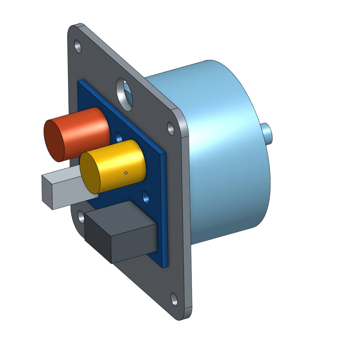
Integrated ODrive with the controller mounted on the back of the motor, using a mounting plate. It would mount to the application via the mounting holes on the plate.


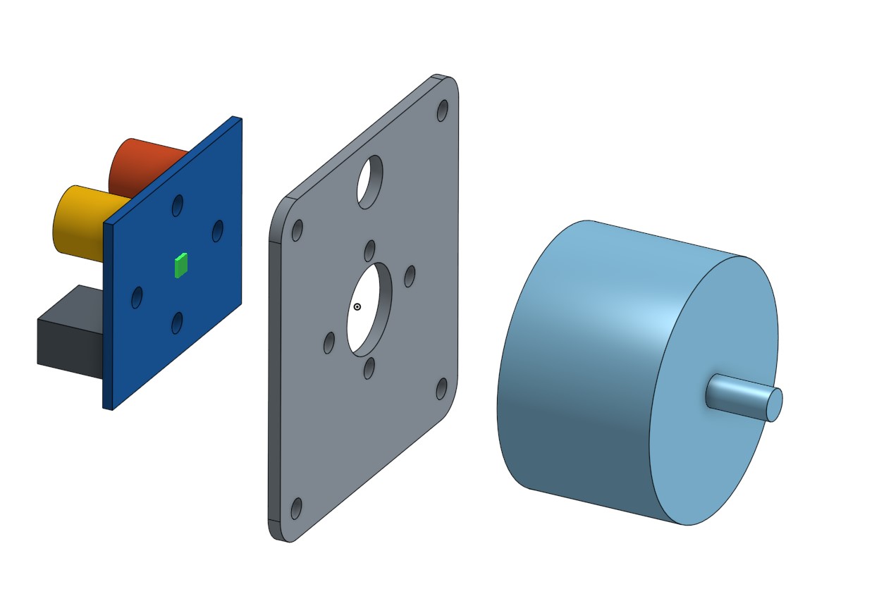
The board has integrated encoder functionality using a magnetic encoder chip, shown in green.

Drone motor
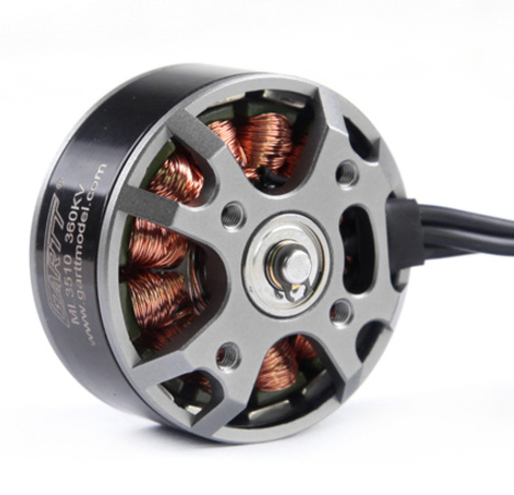
The “short and wide” motors that are designed for multirotor drones would fit very well with this small form-factor. We can glue the encoder magnet to the exposed shaft end.


View of board top side. Left to right: IO cable connectors, USB connector, Screw terminals for DC and brake resistor, Low ESR bus capacitors, 3-phase bridge with heatsinks and brake chopper, 3-phase surface pads.


View of board bottom side: Left to right: CAN tranciever, STM microcontroller, TI DRV8323RS (3-phase gate driver, 3-ch shunt amplifier, buck regulator), ams AS5047P magnetic encoder chip, shunt resistors.


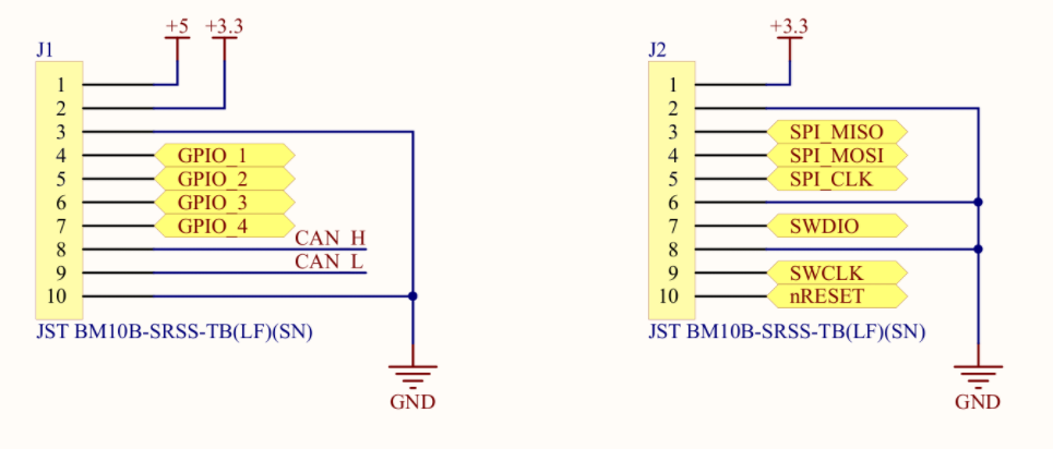
The drive would come with two pigtail cables with connectors that match the IO ports. Above is the proposed pinout. The GPIO’s would have similar capabilities to the current ODrive. The SPI port is not shared with the gate driver here.

Specs

  • 24V bus voltage
  • Designed for 40A continuous, 80A peak.
  • 4096 count/turn absolute magnetic encoder, 0.8deg accuracy (0.1 deg hopefully with calibration)
  • CAN transceiver, for connecting multiple motors together
  • USB port, same interface as regular ODrive
  • 4 GPIO pins (step/dir, UART, PWM, etc)
  • Communication dedicated SPI port
  • Drone style motor (short/wide), 400W-1kW (TBD)
    • 0.5 - 1 Nm, ~8k RPM (TBD)
  • Mounting bracket

The absolute encoder means that all calibration can be done only once, and then the ODrive is immediately operational upon power-up.

A multi-axis system can be done with multiple small ODrives, or a combination of small and regular ODrives, communicating over CAN. Personally I find a Cartesian system particularly interesting where you would have X/Y on regular ODrive, and Z can be the light-weight integrated ODrive. Same goes for shoulder vs wrist motors on a robotic arm.

Would you buy it?

  • I am interested in buying the integrated ODrive with motor and bracket for $139.
  • I am interested in buying the integrated ODrive (PCB and cables only) for $89.
  • I think the regular ODrive better suits my needs due to its specs
  • I think the regular ODrive better suits my needs due to price/value

0 voters

What should we call it?

  • ODrive s
  • ODrive one
  • ODrive mini

0 voters

If you have any other name suggestions, please reply with them.

Discussion

Discussion is very welcome, please let me know what you think.
Thanks!

3 Likes

Great work .
I tried you could sell a few of these!

Teknic sells a version of this that I’m using.

https://www.teknic.com/model-info/CPM-MCVC-3421S-RLN/

They sell less expensive versions as well. I had to disassemble it because I had to resolder the USB connector. It’s very straightforward so getting one to reverse engineer might be worth it.

From my implementation, I realized that the cost/benefit of adding the amplifier to the motor should be examined a bit more. While it simplified the cabling a little in that the encoder (5 wires) and commutation (3 wires) are handled at the motor, it still needs power (2 wires) and a torque and enable signal (4 wires since each signal requires its own ground.) The motor also has a configurable output (I’m using it as a tachometer) that adds another 2 wires. So I’m back up to 8 wires, though only 2 are heavy gauge. With this ODrive design, the CAN transceiver would simplify the wiring, but there would need to be a command set to accomplish what others do with IO. I’m also not sure you want to enable the motor over CAN, as having a separate IO signal may be more robust. That being said, as Oskar said, where it makes sense I think it’s a great option.

Also, I get nervous when I hear glue discussed with high performance machines! A user mountable version with the variety of motor options out there could be more trouble than it’s worth…

1 Like

a note on the magnetic encoders, they tend to be very inaccurate, Bar (the maslow buy) did the Makesmith desktop CNC a few years ago using them and found lots of problems.

To calibrate them, you need to turn them a fixed amount and see what the encoder reads. Can the ODrive be used to drive a stepper? If it can, then you could temporarily couple a stepper to the BLCD motor to rotate it a precise amount for the calibration stage. you would need this to get to even 0.9 degree accuracy.

Bar can go into more detail on the problems he had with them.

2 Likes

I’ve found the same. I would love to see some high quality encoders from a company like CUI.

A single motor driver is a good idea, but with reservations.
At first, there is a tendency to equip BLDC referred above (big diameter, short axial size, a lot of poles) by the magnetic encoder. Encoder integrated by motor probably is a better solution that encoder integrated by the driver.
A second, there are at least two areas with substantially different requirements: CNC and CNC-like devices and “new generation robots”. Distinctive features of last one:
[1] Bigger number of motors that should provide coordinated moving (up to 18 and even more). This means that single motor drive is a preferable solution,
[2] In a difference with CNC, new generation robot intended to use in non-special environment where any moment some obstacle may affect moving, and such situation is not a failure rather routine sequence of events that of course should be processed by parent unit that control a few motor boards. So motor board should be programmed to notify parent unit about the impossibility to execute the command.
[3] A huge number of motors makes step/dir mode impossible or unreasonable; a reasonable way of providing coordinated moving by a few motors is to load kind of moving short program prepared by parent unit into each controller then command to start.
[4] Points [2] and [3] means that mission-dependent part of controller code must be written by the customer. To be able to do this, customers require detail description of the source code and clear separation of two segments, common segment, and mission-dependent segment. PID-based control must be part of the mission-dependent segment that can be replaced or modified by the customer.
[5] USB as the main communication channel is questionable in case of a huge number of actuators; CAN and serial one are preferable, but USB is useful for board reprogramming.

3 Likes

Putting heatsink on the case of the mosfet is not very good solutions for cooling since mosfet case has bad thermal conductivity. The best way to cool dowm mosfets it to put thermal vias to transfer the heat to bottom layer and but heatsink on bottom layer.

2 Likes

This is definitely interesting. Personally I think a step-direction interface is a must for this single motor board, since that would turn it in to a drop-in replacement for stepper motors. For that reason I also think high torque is important, at least 1 Nm (preferably as high as 1 Nm continuous and 2 Nm peak). Most servo applications may still require gearing of some kind, but the lower the gear ratio the better (and when you can go directive drive that’s fantastic)

Naturally this has applications beyond stepper motors, so a drop-in replacement for steppers is far from the only use. I’m just saying that it should have this ability.

With calibration the magnetic encoders can turn out quite well, and could easily be calibrated using a high resolution optical encoder at “the factory”. The question is how often this process must be repeated by the end user? If necessary, I’ve been thinking that temporarily attaching a flywheel to the motor axle could also be used to calibrate the encoder. Spin it up to speed at low current and figure out the inaccuracy of encoder by assuming that it rotates at a constant speed, and comparing the calculated position to position reported by the encoder. The flywheel just needs to be big enough to filter out the torque ripple in the motor to a level below the desired tolerance.

1 Like

Yes, I was thinking to offer the biggest motor that makes sense, mostly for the torque capability, for this very reason. Later we can expand the supported motors (at least sold from ODrive Robotics) to some cheaper ones too. Indeed it will support step/dir from day 1.

Yes I was thinking that perhaps we can use just the rotor’s inertia alone to calibrate. The basic version would be to spin as fast as possible, to raise the torque ripple frequency as high as possible, to let the inertia filter as much as possible. The improved version would be to spin at 100%, and also at 70% or so. Then we can compare the calibration curves between the two. Because torque ripple is an acceleration (not a position offset), we should be able to discern the two, and get the torque ripple map and position offset map at the same time. At least I believe there should be enough measured dimensions to do this with the two speeds.

Giving some thought to single drive board could you include option to use optical encoder instead magnet type.
One big advantage with high torque motor to easily build XY slides any length with static lead screw and spin motor with nut round shaft.
So no high cost machining to shaft just saw to length and clamp to machine.
Also no whipping shaft with smaller diameter can be used for longer travel.
Plan use hollow Gimbal type motor then fit adjustable nut and bearings fitted to carriage.
Think this could make building many types machine lot quicker and more accurate.
Paul

1 Like

Hello,
i am new here.
Is this a current design or pre beta? :slight_smile:
I want to start with the odrive Topic and search a small PCB to manufacture in china.
I am able to open Altium Files and i am also able to do measurements to help you.

Greetings from Germany

Hi Spechtrap,
This design is not finished yet, and so you would not be able to manufacture it. Actually I am not entirely sure we will be releasing the board files, it is a business decision that we have yet to finalize, so we’ll see.

Either way, when the design is done we’ll certainly need testers, so make sure to keep an eye out for the announcement.

Cheers,
Oskar

2 Likes

Very much agree with this post.

Any updates to the single channel odrive concept?

ODrive v4, which Oskar is currently developing, will be a single axis. I’ve also developed a single-axis iteration based on v3.4 architecture.

1 Like

Rad! Looking forward to it.
Do you have the design files for the single channel variant handy by any chance?

I really want to release them and wish I could, but I completed it through my work at an engineering company and they are not allowing me to release the files. For what it’s worth, I’m planning on making my own iteration in late April.

1 Like

pjhayton, did you have to change the firmware a lot? I’m working on single axis board too and wondering what happens when odrive firmware finds out second motor driver IC is not present.

Only for the first iteration, because I took off the CAN IC (so I had to debug through the firmware and comment out any calls to CAN) so that was a nightmare.

With my latest rev, which includes CAN, I hardly had to change the firmware. I only changed the firmware to update my shunt resistance values, the dead time clocks (due to me changing the low-side gate resistor values), and my tup.config file to v3.4-24V.

Thank you for the insight. I hope this can become a community project cuz many people are interested in it. Please do share with us when you get the next design going.