If you could give a bit more detail about what problems you are running into we should be able to help you out. Without knowing more about your application and what problems you are running into it is difficult to give you any kind of direction. 400 pulses per revolution should be fine for many applications.
What motor are you trying to use the encoders with?
Yes, of course. The original ODrive encoders were 600ppr (2400) cpr encoders. Make sure you’re using 4x the PPR as your CPR (so, likely you have to put 1600 for odrv.axis.encoder.config.cpr)
I have chanced the settings I needed to change (it think)
I can run the calibration but then if I try to run it in closed loop control, it doesnt do anything. If I type the encoder error thing I get 0x2 but I don’t know what it means because it is not in the list.
So I think that maybe my encoders are fake or something. So I was thinking on maybe using the cheapest encoders ever because I don’t need the resolution. Something like this https://s.click.aliexpress.com/e/c2bZFg6G but I don’t know if that’s possible. And if it’s possible to solve my problem with the other encoders I would like that the most. (Because my project is designed for this encoder). Someone told me something about a command to turn the encoder by hand to see the resolution if you don’t know it, maybe I can give that a try but I don’t know the command.
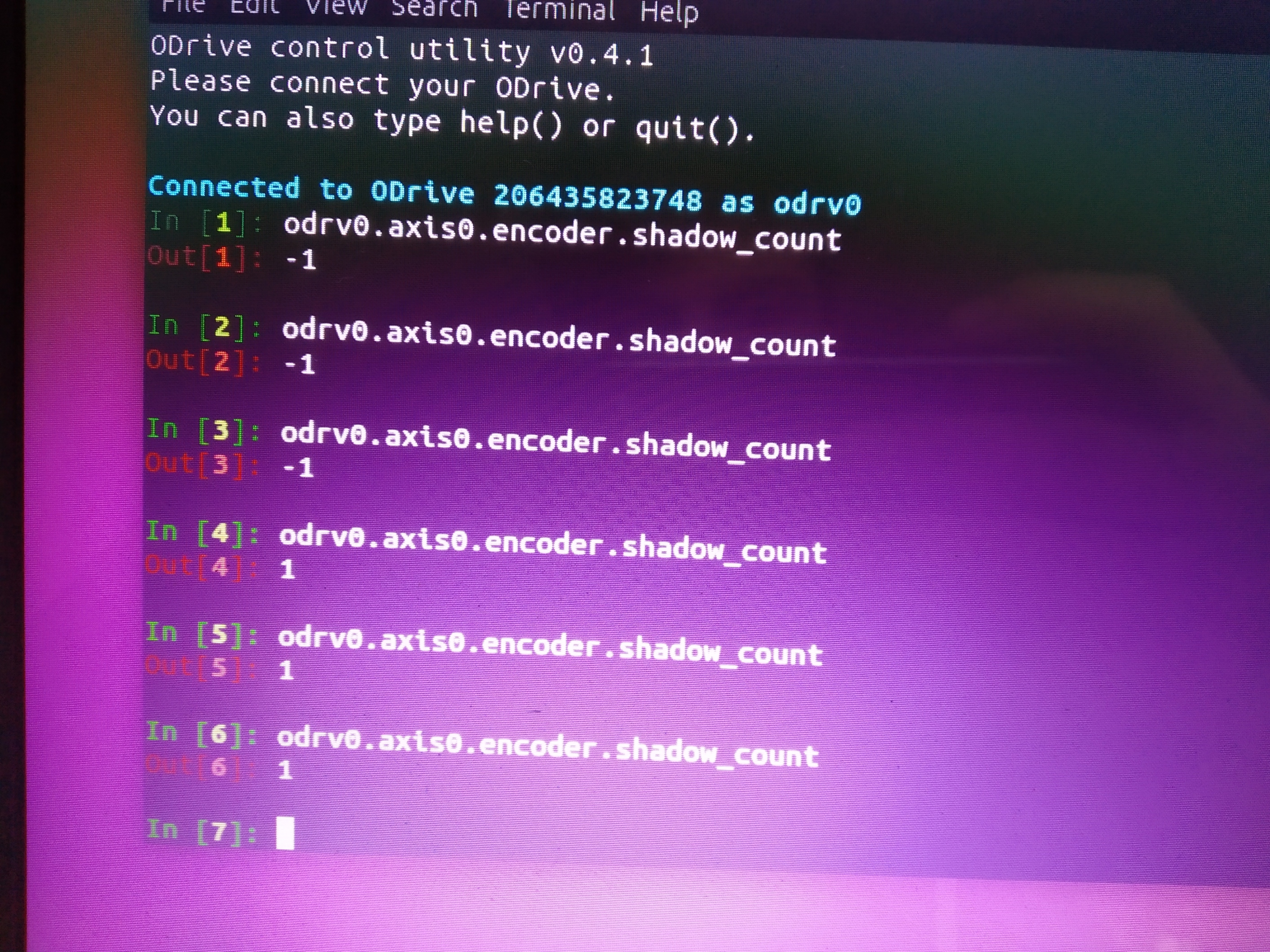
Have you verified that shadow_counts is changing when you manually spin the motor with the encoder attached?
If you are seeing that value change then the next step is to verify the number of pole pairs that your motor has. This is done by counting the number of “cogs” that you feel when spinning the rotor through a full revolution and dividing that by two. Is that number set the same as what you have configured for pole_pairs in the odrive?
During the calibration routine the odrive attempts to correlate the electrical phasing of the motor to the encoder. There is simple relationship between the mechanical rotation of the rotor and the rotation of the electrical field that the odrive generates in order to spin the rotor. This difference in scale between the two is related to the number of pole pairs the motor has, so if that isn’t configured correctly your motor won’t spin.
Now I get -1 whatever I do, I’ve turned the motor a few times but it doesn’t change and when I switch the A and B lanes I get 1 also when I turn the encoder.
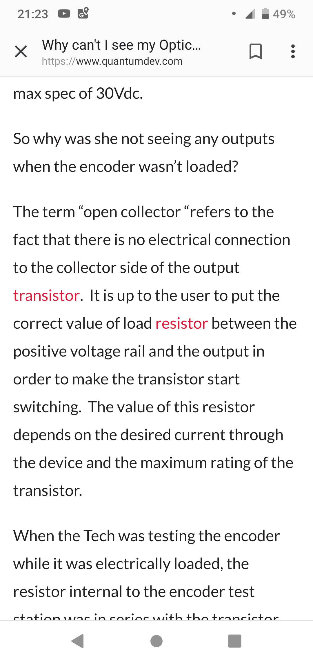
The encoders that you have are open collector output. The product page mentions the need for resistors between your supply voltage and the transistors that are on the A and B channels. I am not sure if the odrive is setup for open collector or push pull encoders.
I can dig into the details of this a bit later, but this is a good reference to get you started in understanding the different types of encoder outputs.
If the odrive is setup for push pull rather than open collector you may need to wire up an external resistor between 5V and the A/B pins to get your encoders to work.
Hold the phone. It looks like 0V needs to be wired to the A/B pins, not 5V. I think the resistor needs to go on the supply connection, not the connection between A/B and ground. It may not matter either way, but please don’t take my word for it. Do a bit of homework on NPN open collector encoder outputs to see the recommended way to wire them up.
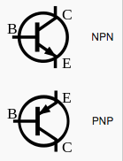
Just be aware that there are two different types of open collector circuits. One is specific to a PNP transistor and the other is specific to a NPN transistor. Your specific encoder seems to use NPN transistors.
Ok, I’ve got it straight now. It’s been a little while since I’ve worked with transistor outputs, so I had to do a bit of reading to refresh my memory.
If you look at the transistor in the CUI link that I put in an earlier post you can see from the symbol that it is actually a NPN transistor in the circuit that they are describing for the open collector type of output. This means that you should hook up your encoders exactly as they have depicted in the article.
You can use a 1K resistor between 3.3V and the A and B pins on the Odrive and then hook up the wires of the encoder as you normally would.