[Solved] The Hall sensor pull-up resistor is strange

Hi. I have a weird problem

Encoder pull-up resistor is strange.

I am using a V3.5-48V ODrive.


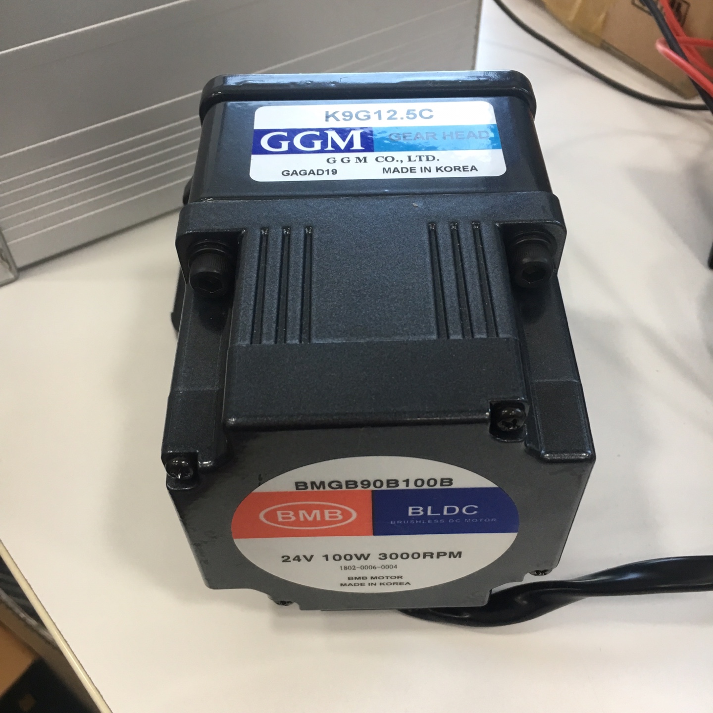
The motor uses BLDC 24V, 100W, 3000RPM.
Gear ratio 1: 12.5
(motor information is in English, sorry.)

This motor uses Hall sensors on M0.
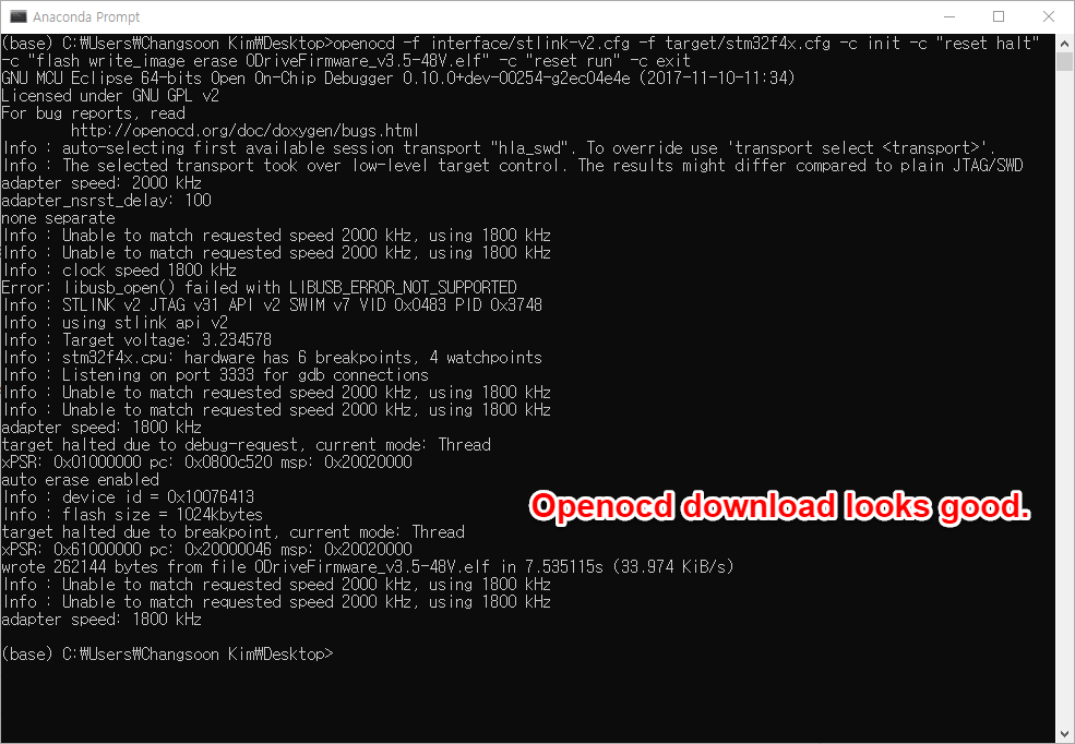
With reference to the hover board guide

odrv0.axis0.requested_state = AXIS_STATE_MOTOR_CALIBRATION

odrv0.axis0.requested_state = AXIS_STATE_ENCODER_OFFSET_CALIBRATION

And there were no errors.

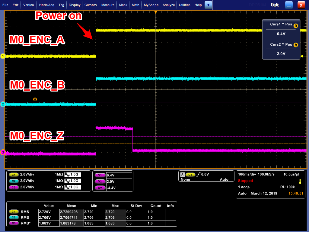
But…I checked the hall sensor waveform with the Oscilloscope
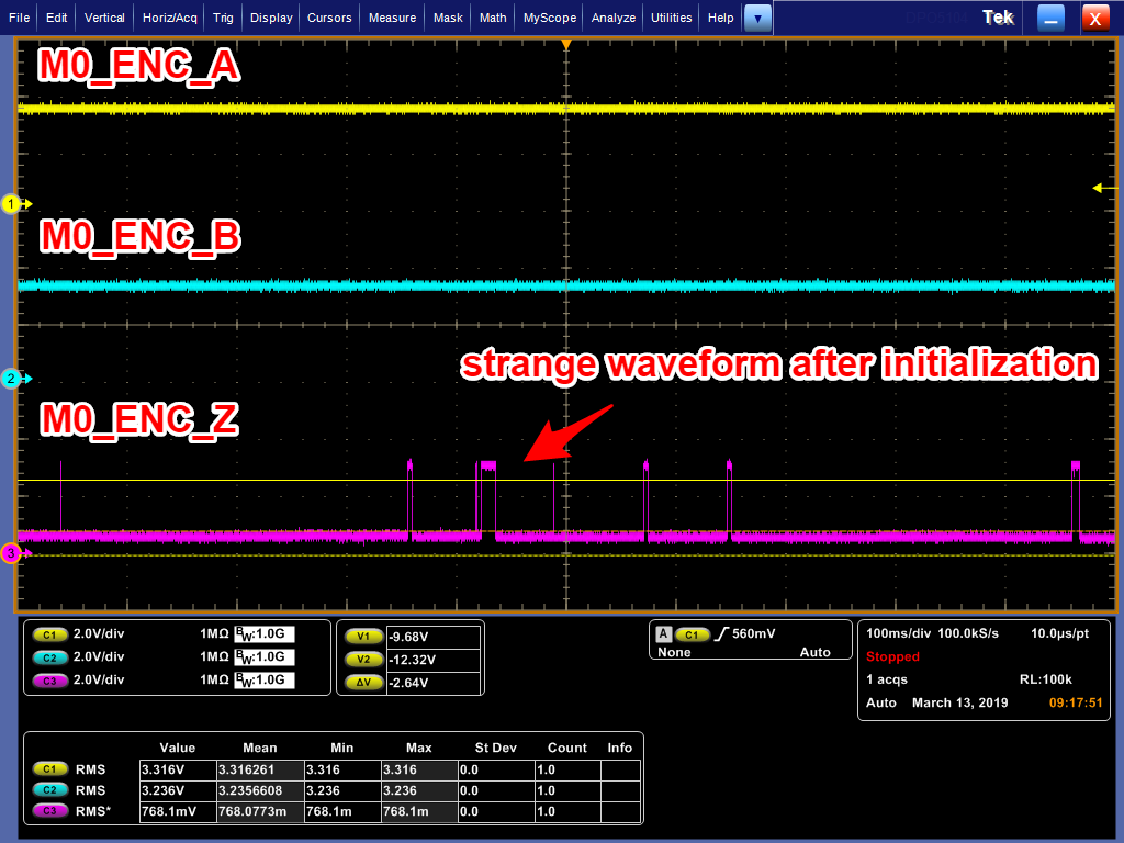
When ODrive power on, waveform of M0_ENC_Z should be 3.3V, but it is abnormal.

I think it is something wrong…

  1. Hall sensor connected : M0_ENC_Z is 0.8V
  2. Hall sensor not connected : M0_ENC_Z is 2V

The M0_ENC_Z waveform is also strange when turned by hand.

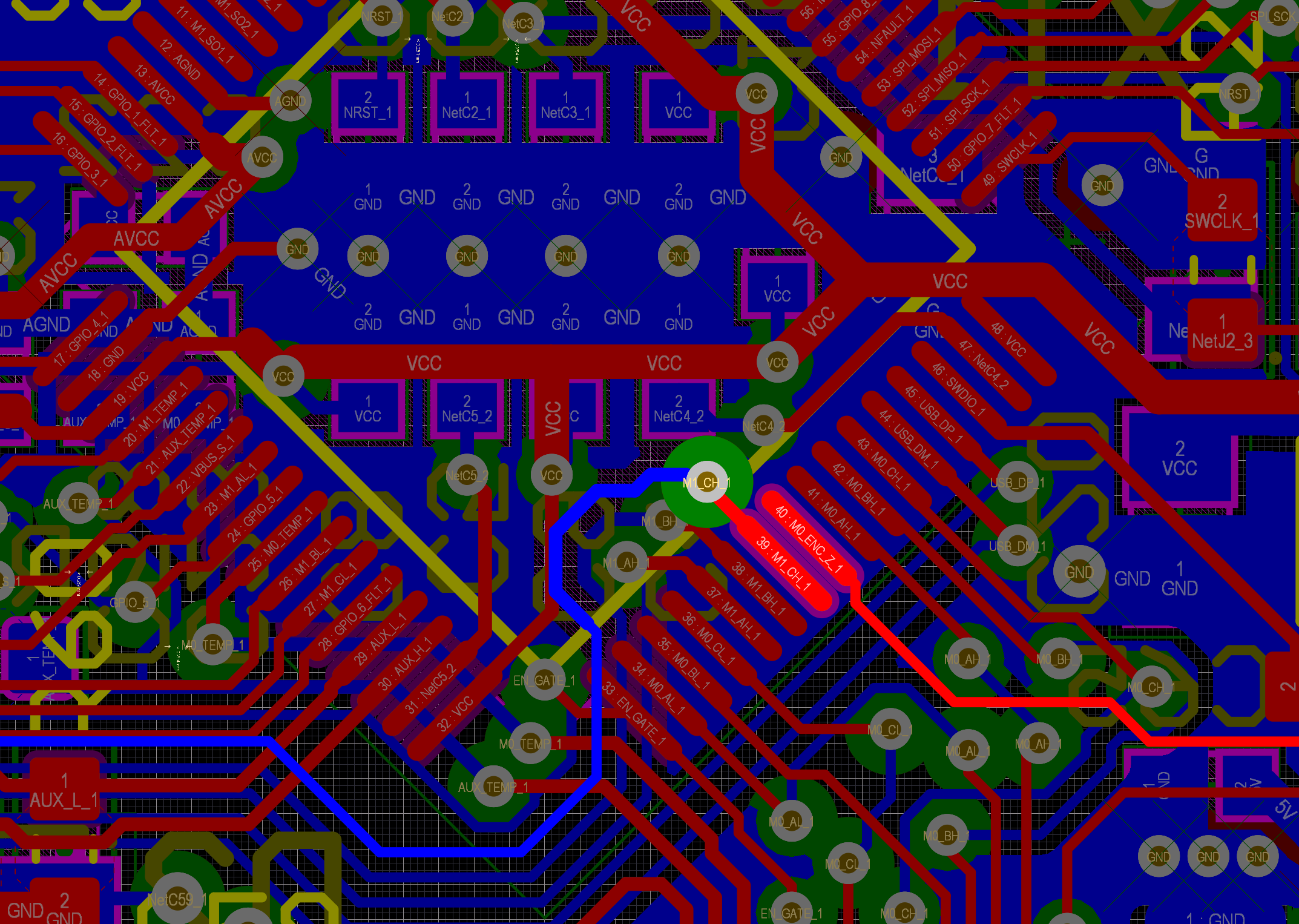
Pull-up resistor abnormal symptoms.

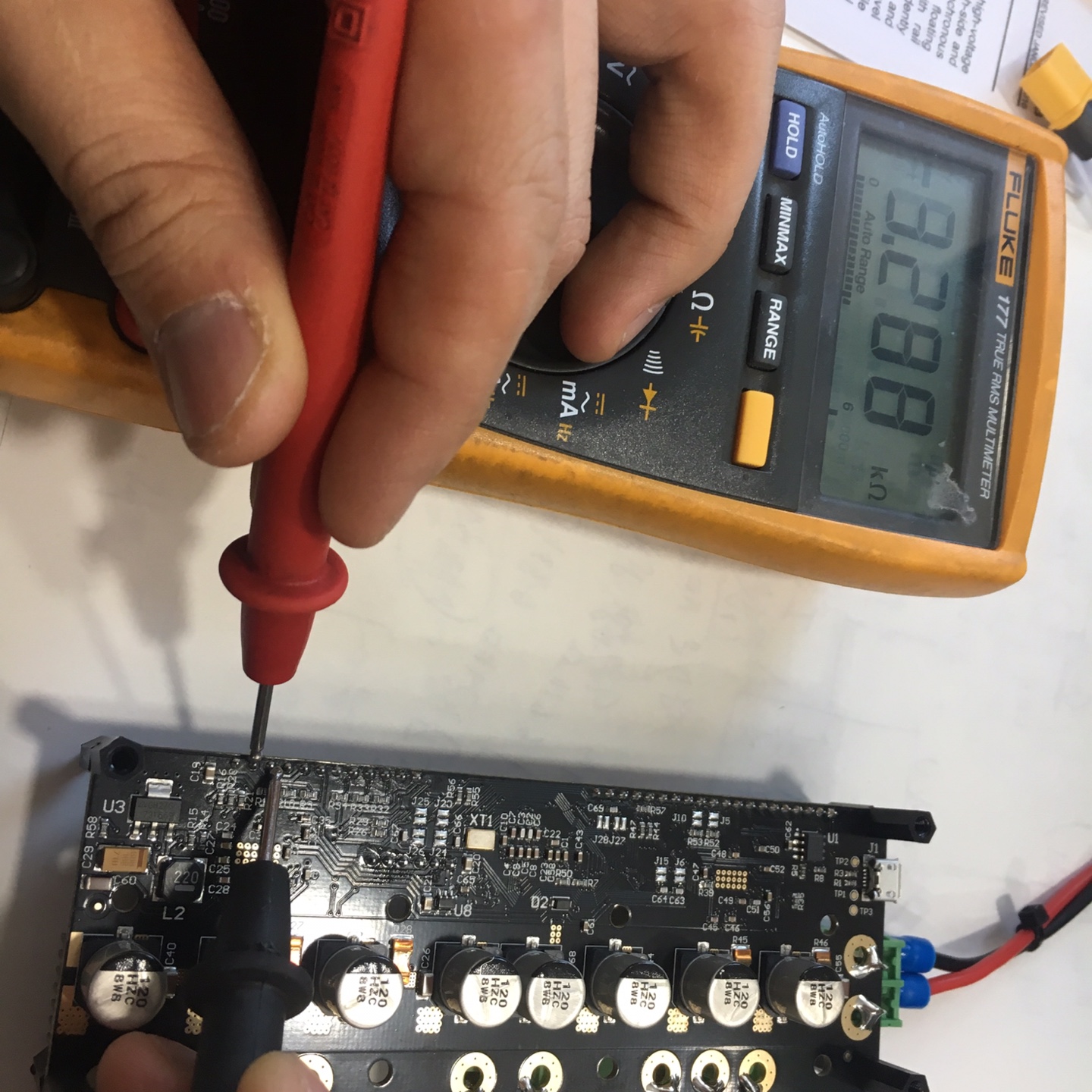
  1. Pull up resistor resistance between M0_ENC_A and M0_ENC_B
    6.63Kohm => It looks okay.

(The M1 is normal with a resistance of 6.63Kohm, regardless of which pin is selected.)

  1. Pull up resistor resistance between M0_ENC_B and M0_ENC_Z
    3.299Kohm => abnormal
    And… R11 Measured “81 ohm” in soldered condition.

I have not changed the resistor yet, but it is very strange.

I already seen other posts.(this & that) but i thought that it isn’t my case.
Thank you.

Eventually… the R11 pull-up resistance became 2 ohms (original 3.3 kohm).
I just turn on/off repeatedly for measuring waveform using oscilloscope.
Resistance does not work. Both ends of the resistor are connected…
3.3v was input directly to the M0_ENC_Z pin.
The pin seems to died. : /

I want to find out why the resistance is dead. :frowning:
Was it burned because of resistance load?

That is not normal. Please try to replace R11 with a 3.3k resistor. If that doesn’t work then it’s likely something broken in the STM32 microcontroller pin. In that case do you have the available equipment to change the microcontroller?

@madcowswe Thanks for reply. :slight_smile:

Eventually I replaced the MCU.

  1. Test Firmware
    I write some simple firmware that toggle pin every 10ms period Firmware
    (toggles the M0_ENC_A, B, Z pins.)
    M0_ENC_Z pin is dead as i expected. it doesn’t any movement.

  2. Replace the MCU(STM32F405 RGT6)
    The R11 resistance removed.
    (It is normal state… i check R11 resistor is 3.3Kohm)

  3. Toggle the M0_ENC_A, B, Z pins using same test code.
    Confirmed very well (with 10ms cycle delay)

after that, i soldered 3.3kohm resistor.

  1. Download the latest firmware version V3.5-48V. (0.4.8 version)

  2. M0_ENC_A, B, Z should be pulled up to 3.3V when power is turned on.
    But it is pulled up and goes down to “LOW” after 120ms.
    (At this time, the motor hall sensor is not connected)

Very, Very weird waveform as i seen.

  1. Change to M0_ENC_A, B, Z pin input mode (in My test code)
    I changed M0_ENC_A, B, Z to input mode and download.
    Turn motor axis by hand and check that the waveform is input normally.
    it is clearly normal.

Summary

  1. M0_ENC_A, B, Z pins are normal after MCU replacement.
  2. If it is normal, i thinks that M0_ENC_A, B, Z pin is pulled up 3.3V after power ON.
  3. Change the M0_ENC_A, B, Z pins to input mode, and check the hall sensor.

MCU Pins / Hall sensor is normal state.

Question
The remaining part is the source code.(Release version 0.4.8)
Is there any item to touch the setting of M0_ENC_Z pin after initialization in MCU?

Thank you in advance.

My board version is V3.5 / 48V Version.
The firmware version is the latest 0.4.8 version (ODriveFirmware_v3.5-48V.hex)
In my case, I just downloaded it at https://github.com/madcowswe/ODrive/releases.

PC (STM32CubeProgrammer) => ST-LINK V2 => ODrive.
(STM32CubeProgrammer can download hex and elf files just like Openocd.)

In the post, I used “STM32CubeProgrammer”, but I tried downloading it with Openocd. The download went well without any problems.

However, when I check using the oscilloscope, the same symptom appears in M0_ENC_Z immediately after initialization.
And strange waveforms appear right after initialization …

There might be something wrong at the board.
I’ll check both the circuit and code.

Board already cleaned by pcb cleaner.

@madcowswe

Through debugging, I found a point that M0_ENC_Z pin to LOW!!!

main.cpp => start_pwm(&htim8); => HAL_TIM_PWM_Start(htim, TIM_CHANNEL_3);

This code immediately drops the M0_ENC_Z pin to LOW after MCU initialization.

Checking from ODrive pinout document, pins corresponding to
TIM8_CH3 is PC8 (M1_CH).
TIM8_CH3N is PB1(M1_CL), PB15 (M0_CL).

All are pins associated with the DRV8301 Gate driver.
What do these pins do?

I will investigate further.

Wow nice job in digging so deep. Yes the pins related to TIM8 are all going to the gate driver like they should. However check this out:

The M0_ENC_Z is right next to TIM8_CH3. There is likely a solder bridge or defect in the PCB that is connecting them together. The defect has to be right under the MCU chip, because the traces go in different directions:

This is clearly our fault, and we can supply a replacement board free of charge. I will email you about that.

@madcowswe

I will email you about replacement.

Thank you for revealing the cause!!