Hello,
I have to take a break with my ODrive 48V project, because a spark damaged the board.
Before that I tested a setup with an old ATX power supply (12V, 17A)
Movements with “demo.py” or positioning with “Explore_odrive.py” were possible.
But holding the spinning motor by hand or faster velocities after increasing “.vel_limit” to “200000.0f,” (for my setup 3000 rpm) turned off the power supply.
I measured the current going from supply to ODrive. I had wondered why the power supply turned off if the current never went over 7 A. Maybe some current peaks and not enough available power!
(Measurement with an analog Ampere Meter, DC, 0 -15 A)
So, I ordered a Mean Well RSP-3000-48 (48V, 62.5A)
Another hardware:
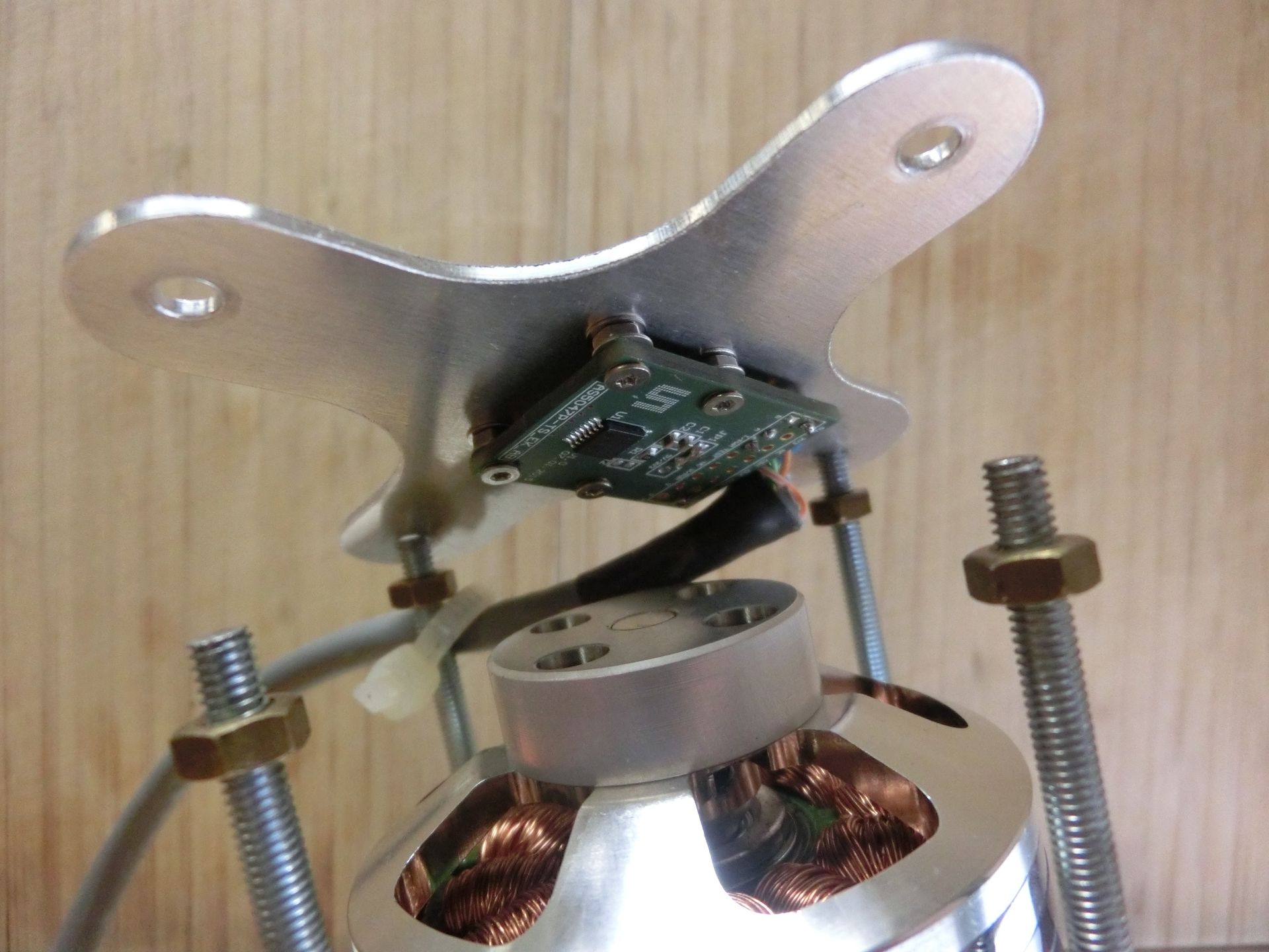
motor: Turnigy Aerodrive SK3 – 6374-149KV (Max Speed 48V x 149kv = 7152 rpm)
Encoder: AS5047P Adapter Board
4000 steps / 1000 pulses per revolution || Max speed 28000 [rpm] (tested with Arduino)
Firmware ## [0.3.4] - 2018-02-13
Changes:
Inc\main.h:
#define HW_VERSION_HIGH_VOLTAGE true
low_level.c:
#define ENCODER_CPR (1000 * 4)
.pos_gain = 120.0f,
.vel_gain = 10.0f / 10000.0f,
.vel_integrator_gain = 100.0f / 10000.0f,
.current_lim = 15.0f,  //[A]
disabled Motor 1
// .enable_control = false,
New power supply
The more powerful power supply [Mean Well RSP-3000-48 (48V, 62.5A)] was delivered and I decided to make the first test run with 48V. I was using the same firmware but only limited “.vel limit” and increased “.current lim” in low_level.c:
.current_lim = 30.0f, //[A]
.vel_limit = 20000.0f, // [counts/s]  (300 rpm)
(20000 counts x 60s / 4000 counts per round = 300 rpm)
First, I adjusted the naked power supply from 46V to 48V and nothing else connected.
Then I connected the power supply with the ODrive and prepared to start “Explore_odrive.py” to make tests.
I turned the power supply on, the multimeter showed further 48V, the Motor calibrated, slowly left and right and then it accelerated extremely fast to maybe top speed within two seconds. I saw and heard a spark on the board. I turned quickly the power supply off.
ST-LINK V2 measuring:
I disconnected everything from board except ST-LINK V2 and plugged it to a USB power meter:
At beginning it shows 4.25V and 0.64A, the green power LED was shining.
After two minutes it shows 4.75V and 0.21A, the green power LED was shining but really dark, Motor Driver U4 and the ST-LINK V2 gets warm.
I decided to plug it in my PC to make sure that the microcontroller is still working.
I tested to flash the board with the current Firmware, but…
“Info : Unable to match requested speed 2000 kHz, using 1800 kHz”
“Info : Unable to match requested speed 2000 kHz, using 1800 kHz”
“Info : clock speed 1800 kHz”
“Error: reset device failed”
“in procedure 'init'”
“in procedure 'ocd_bouncer'”
… I removed the ST-LINK V2
After a while I found out how I could flash the “burnt” board! This way:
I plugged it again, waited a while until the green LED got darker. USB power meter showed 4.75V and 0.21A. I prepared VS-Code (“Tasks” -> “Run Task” -> the cursor over “flash”).
Now, I removed quickly the ST-LINK V2, plugged it quickly in and pressed the mouse button to begin flashing:
adapter speed: 2000 kHz
adapter_nsrst_delay: 100
none separate
Info : Unable to match requested speed 2000 kHz, using 1800 kHz
Info : Unable to match requested speed 2000 kHz, using 1800 kHz
Info : clock speed 1800 kHz
Info : STLINK v2 JTAG v17 API v2 SWIM v4 VID 0x0483 PID 0x3748
Info : using stlink api v2
Info : Target voltage: 2.672192
Info : stm32f4x.cpu: hardware has 6 breakpoints, 4 watchpoints
target state: halted
target halted due to debug-request, current mode: Thread
xPSR: 0x01000000 pc: 0x0800a448 msp: 0x20020000
auto erase enabled
Info : device id = 0x10076413
Info : flash size = 1024kbytes
target state: halted
target halted due to breakpoint, current mode: Thread
xPSR: 0x61000000 pc: 0x20000042 msp: 0x20020000
wrote 131072 bytes from file build/ODriveFirmware.elf in 6.786136s (18.862 KiB/s)
I think the the board was flashed successfully, but I can’t test it because when I connect for example the 12V ATX power supply then this power supply turns immediately off.
How does it go on now?
What caused the damage?
Maybe the strong magnetic field with 48V on the shaft that influenced the small magnet and the magnetic encoder. Should I’m using another encoder like the CUI AMT102 capacitive encoder next time?
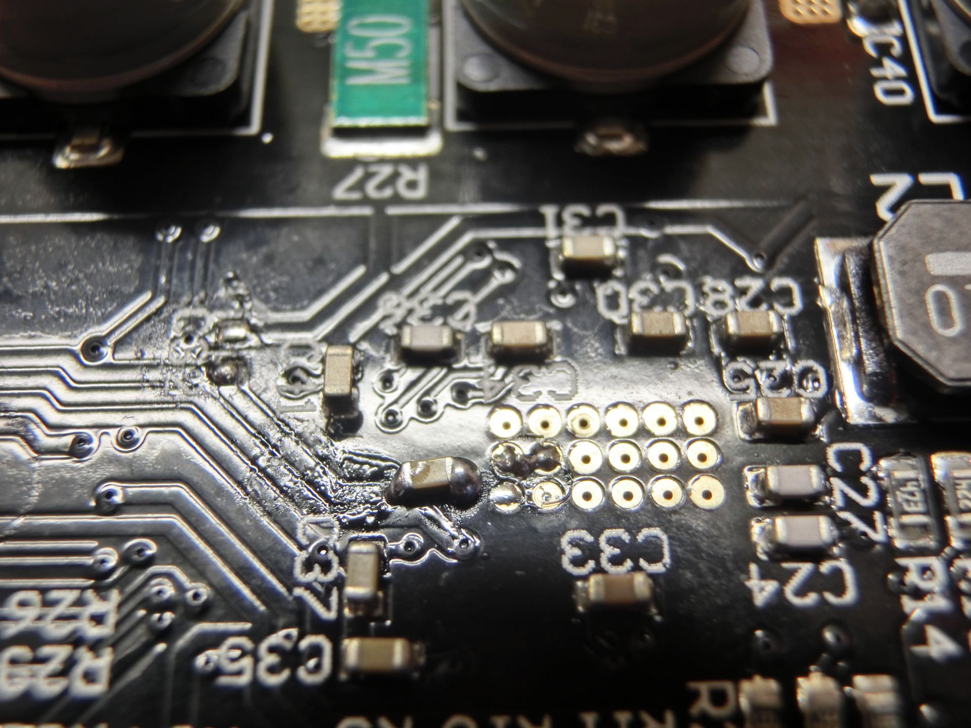
[Or could be the reason a not good soldered Cap “C32” under the other side under the warm M0-motor-chip? Resolder it? (I posted here something similarly)]
How can I make it work again? Replace the U4 motor controller for M0? I don’t really know. Any idea?
with best regards,
Tom