Hi Nathan,
Thanks for sharing ! It’s a really cool project. I have read your code seriously except Odrive fork. There is one question here. Could you please help to answer ? Thank you very much.
1-Is there some materials to guide how to connect pins between Odrive, Teensy 3.5, motors, IMU, Xbee and AS5047P encoder ?
Hi Jackie, unfortunately, we currently don’t have a lot of information about the specifics online so this will be a start. Right now we kind of leave it to the builder to reference the ODrive documentation. Anyways, starting with the ODrives, the motors’ phase wires are connected to their respective pads on the ODrives. The AS5047P encoders’ ABI interfaces are connected to their respective pins on the ODrives. Finally, each ODrive is connected to the Teensy via the uart serial connection, which means connecting the ODrives’ GND, TX, and RX pins to their respective serial pins on the Teensy.
As for the parts connected to the Teensy, the IMU is connected using the SPI interface and the XBee is connected via uart serial. For now however, we only use the IMU for sequencing the different commands involved in performing a backflip. Hope that answers your question!
Hello Nathan,
Thanks a lot for your reply. I think it is a best way to try it in practice. We are on the way. You said that “we only use the IMU for sequencing the different commands involved in performing a backflip”. It is true after reviewing the code. I am very surprised and it is a great idea. How do you come up with this idea. Could you please help to share some stories ? Is it from one cited reference in your paper ?
Hi Jackie, I’m super excited that you’re well on your way to building your own. Looking forward to any updates! I think the idea of using the pitch angle of the robot to sequence the commands during a backflip came naturally out of just trying to figure out how people or animals do any sort of maneuver. We basically just looked at a few videos on youtube of how dogs do backflips and saw that there were a few different stages of the backflip that are triggered at different angles around the backflip. But more seriously, using the pitch angle is kind of a bare minimum level of state-based feedback control and it worked really well for us. It also made it really easy to tune. Our backflip could be contrasted to how the mini cheetah does it, which is by computing a torque profile offline via nonlinear optimization. That method intuitively is more flexible and general, but honestly it took us about 2-4 hours to get the backflip working with our janky pitch-based controller. Since we’re just doing this in our free time, we were pretty happy with how it worked out!
3 Likes
@Nathan thanks again! I followed your point about unlimited rotational range at the hip being a bonus but you lost me at the “parallel leg linkage” part. From what I understand, the legs are a 5 bar linkage SCARA. Which bit of that linkage is parallel, and with what is it parallel? Or is parallel a label term for a particular arrangement? Sorry if this blows my cover on my robotics noobness!
I suppose I’m trying to understand what the virtues of your thoughtful/experienced engineering choices are before I embark upon hopefully my own build. I’m seeking opportunities to reduce cost and have identified that the coaxial hip drives could be a good area to cost-optimise and one way to do that might be to have two parallel hip axes rather than one coaxial axis (if that makes any sense!).
Hi Simon, the terms parallel and serial linkages refer to whether you have closed kinematic chains, aka, links that form a loop together. I’d maybe look at https://en.wikipedia.org/wiki/Serial_manipulator and compare it to https://en.wikipedia.org/wiki/Parallel_manipulator.
The Kod*lab, which also developed the Minitaur, built a robot called Inu that does away with the coaxial leg setup for a simpler mechanical design but that also has a more limited leg workspace: https://kodlab.seas.upenn.edu/robots/inu/.
The problem with reducing Doggo’s cost is that the motors and motor controllers alone add up to about $1200, which is still way out of the range of a robotics hobbyist. I’m really hoping that the creators of projects like https://www.youtube.com/watch?v=bnEtJSkUFDk, which use cheap servo motors that do not require motor controllers, will go open source and release design documentation.
3 Likes
@Nathan thanks once again. I agree - for a novice the servo approach is probably the way (and I am a novice). I’m interested in whether some smaller motors with high reduction belt drives could maybe reduce cost. Say a 50mm dia 360 kV motor for $20 with a multimotor variant of OTRESC (https://hackaday.io/project/90283-otresc-bldc-controller). Could be talking $100/ leg at that point for a small robot?
1 Like
A post was merged into an existing topic: How to interface 8 ODriver with Pc when there are too many wires
Hi @Nathan thanks for sharing. Great project ! I have a stupid question. The controller inside Odrive is PI controller. How you guys change it from PI to PD? Is PD controller in Teensy or Odrive ?
Hi tangwy, we rewrote the ODrive’s position controller to use a single PD controller instead of the cascaded position and velocity controllers. Doing this also allowed us to couple the two axes together to achieve virtual compliance in arbitrary frames (ie cartesian or polar frames).
Hi @Nathan, thanks very much for your reply. So do I need to flash the firmware in order to change the control mode ? Maybe this problem is easy for you, but I am new to this area. So if you can explain this, it will be much helpful !
Hi tangwy, there’s a drop-down section called “How to flash a custom firmware” on this page: https://docs.odriverobotics.com/odrivetool#device-firmware-update. Hope this helps.
Hi Nathan, amazing work. I am currently also trying to control an actuator with virtual compliance. The way i intended to implement it was using the regular cascaded control loop of the ODrive. So i have a seperate control loop, which calculates the position input based on the ODrive Current/Torque estimate. I got it sort of working for a simple lever connected to my Motor, but had some issues with stability. Advantage is, that i can program the Force-control on my teensy, but apart from that i’m not sure, if this is really the way to go. Is that setup making the control loop slower or more unstable?
Hi rockz, could you tell me more about how your system works? Is the Teensy doing the controller calculations and sending torque commands to the ODrive? If you the teensy is running the control loop and not the ODrive then that is definitely a possible source of instability because of signal lag and signal rate.
Hi, the contol loop would look something like this. I am using UART to send pos. Commands and read the measured Current.
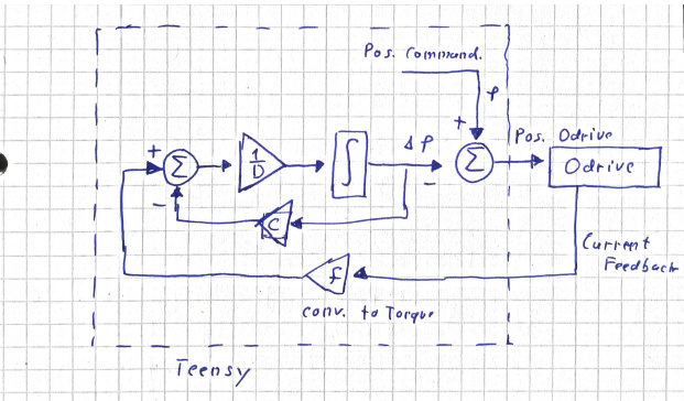
But i just realized it would be much more simple to use simple PD-control of the ODrive by just setting the integral gain to zero.
However, if i want compliance in cartesian space, i need to constantly update the Gains according to the inverse Jacobian. So fast communcation would still be required.
Also (how) did you compensate for gravity?
Hi rockz, our ODrive firmware already supports cartesian compliance! https://github.com/Nate711/ODrive/blob/master/Firmware/MotorControl/controller.hpp. You can use the functions:
void set_xy_setpoints(float x_setpoint, float y_setpoint);
void set_xy_gains(float kp_x, float kd_x, float kp_y, float kd_y);
These functions are visible to both the odrivetool CLI and the python odrivetool library which work over USB. We haven’t made these functions accessible by UART, but you could use as example the functions set_coupled_setpoints and set_coupled_gains available. You’d then have to modify the teensy firmware in like. The only thing is that we didn’t implement gravity compensation, but that was fine for us since our leg linkages are so light.
And by the way, we first worked out the math for the method you describe, where you constantly update the gains, but for this to work you need to send the odrive a matrix of gains (including off-diagonal gains), which the odrive doesn’t support.
Best,
Nathan
1 Like
hello nathan.I was trying to upload your teensy codes(not the odrive one) to teensy3.5 via VS Code and it said upload was successful.But when I tried Serial Monitor,nothing showed up in the terminal.I also tried to upload codes via Arduino and opened the Serial Window,but the same problem existed.
According to main.cpp,the serial should output somethings like
STATES: Danc(E), (W)alk, (T)rot, (B)ound, §ronk, (S)top, (J)ump, (Y)TurnTrot
So I tried to remove all src codes and replaced it with main.cpp shown below:
#include <Arduino.h>
#include <ODriveArduino.h>
#include <ChRt.h>
#include <SparkFun_BNO080_Arduino_Library.h>
void setup()
{
Serial.begin(115200);
Serial.println( “Ready for input”);
}
void loop()
{
Serial.print(“Hello, world?”);
delay(1000);
}
but nothing showed up in the terminal window.Can you offer me a help?
when I just re-download the libraries and tried the simple main.cpp, it worked.Maybe incorrect libraries is the cause.
So someone actually sells Ben Katz’s mini cheetah motors now: https://www.aliexpress.com/item/32985671853.html?spm=a2g0o.detail.1000060.3.3e102ef5X1lUEN&gps-id=pcDetailBottomMoreThisSeller&scm=1007.13339.146401.0&scm_id=1007.13339.146401.0&scm-url=1007.13339.146401.0&pvid=d1c5eb92-8139-4485-b3b1-950fde3ec261
Awesome! Ben had told me he was working on getting the motor mass manufactured in China. Looks like this is a prototype? I think their long term plan is to manufacture dozens of Mini Cheetah robots for labs or hobby use.