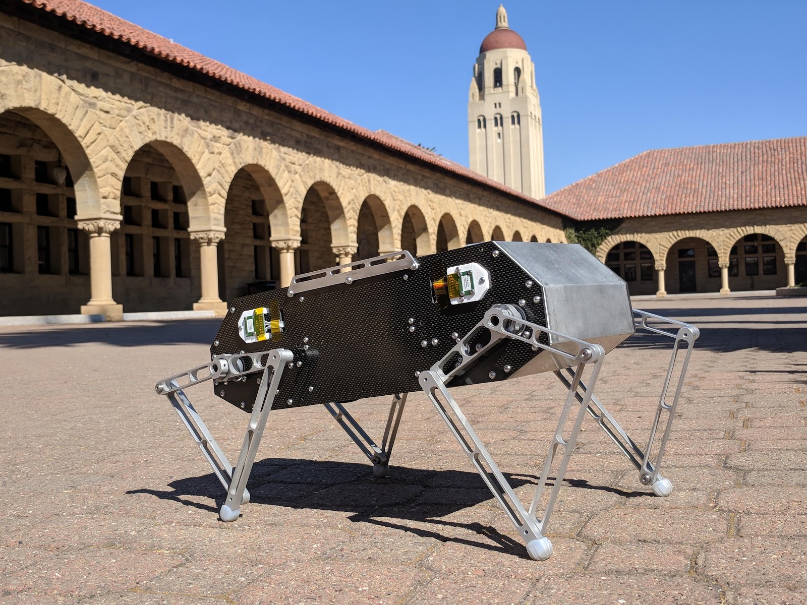
Hi all, I thought I’d share more about the Stanford Doggo Project, which you might have seen in Oskar’s New Year’s update! We’re a group of undergrad and grad students in Stanford Student Robotics and have been working on legged robots for the last year and a half. Our latest robot, Stanford Doggo, is a shoebox-sized quadruped robot that can walk, trot, pronk, and jump around.
I think this video gives the best overview of what Doggo is:
And my favorite video, Doggo doing a backflip:
I’ve been seeing a ton of amazing projects here on the forum and on the ODrive Discord channel, so I wanted to make a blog post explaining how Doggo works. I hope people might be able to learn something from this post, and perhaps even build their own Doggo and improve upon it. The whole project is open-source (links below) with CAD, code, and firmware available on Github. The robot code runs on a Teensy 3.5, and we use ODrives for motor control so I imagine a lot of people here could jump right in. We’ve also tried to make the robot inexpensive to build in your own lab, school, or home, and we absolutely welcome people to contribute to the project.
Relevant links:
GitHub project repository: https://github.com/Nate711/StanfordDoggoProject
Full, downloadable Fusion 360 CAD: https://a360.co/2OBxTbH
Teensy code: https://github.com/Nate711/Doggo
ODrive fork: https://github.com/Nate711/ODrive
Mechanical Design
Coaxial mechanism
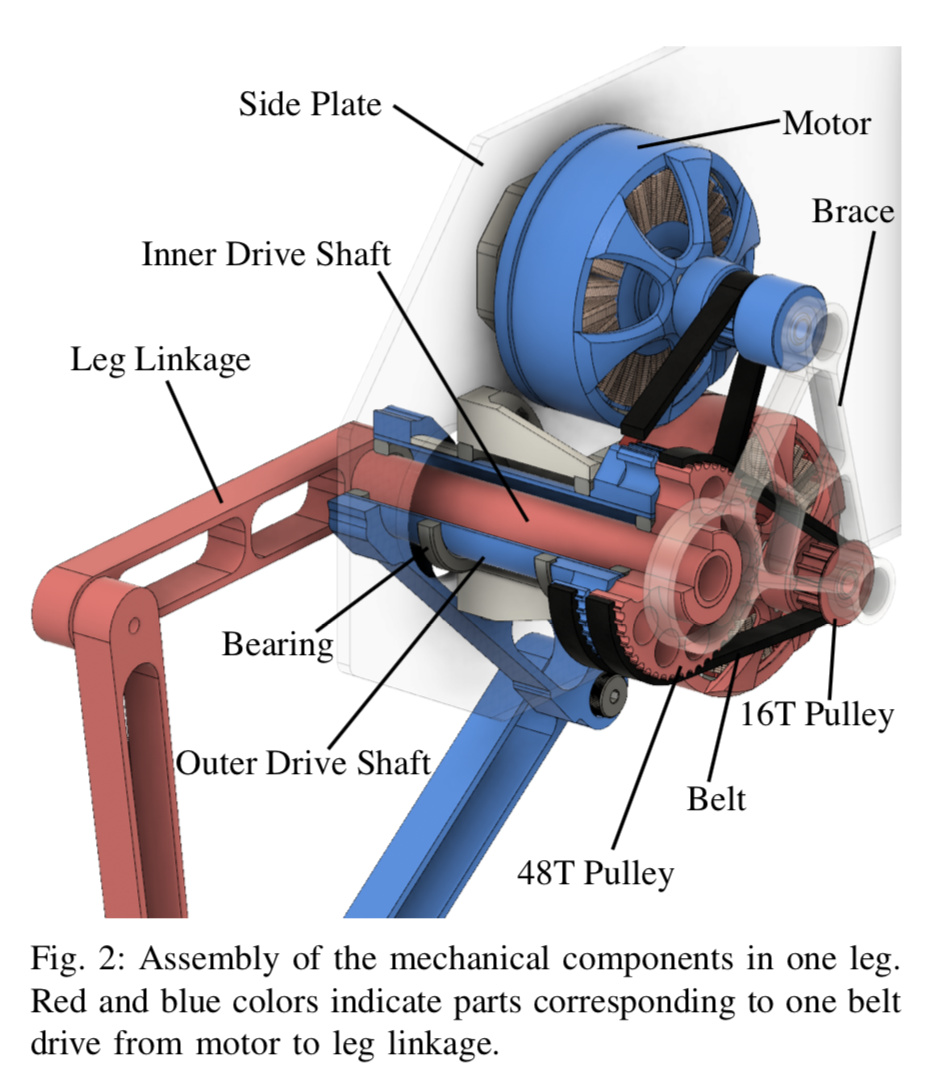
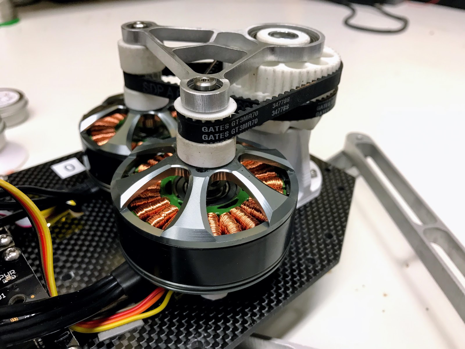
The coaxial mechanism that drives each leg is definitely the most complex mechanical component of the robot. It has also been the most troublesome. The way it works is that we have two TMotor MN5212 motors mounted on the carbon fiber side panel. We also have a 3D printed bearing block that has two bearings to hold the outer coaxial tube. (Refer to the cutaway CAD view below). The two motors transfer power to the coaxial shafts via 6mm wide, 3mm pitch GT2 belts between a 16T pulley and a 48T pulley. We didn’t have room in our mass budget for regular, off-the-shelf pulleys, so we printed our own using the Xometry SLS service. As a side note, we learned to always specify to the service that the pulleys must be printed up. If the parts are printed at an angle, the geometry of the pulley teeth gets distorted because of the off-angle layers. Above the pulleys we have a waterjet aluminum bracket to maintain belt tension and thereby prevent skipping during high-torque situations. That said, it was a real pain to find the best center-to-center distance for the bracket because the slop in the connection between the motors and small pulleys, and the slop in the connection between the larger pulleys and the shafts meant that the center-to-center distance for the top bracket had to be 0.5mm larger than the nominal center-to-center distance prescribed by the belt supplier (SDP-SI). The biggest problem with this assembly was that the higher the belt tension, the more friction we had in the assembly. Higher friction means worse tracking performance for the motors, and also worse sensitivity to touch-down events and the like. On our next robot, we’re hoping to have smoother, more precisely machined pulleys, and less slop in the coaxial assembly.
CAD diagram
IRL
In operation
Legs
Doggo has four, 2DOF legs of the SCARA flavor. By SCARA flavor I mean that each leg is a five bar linkage and the two upper links are driven co-axially. The actual leg links were waterjet cut by Big Blue Saw, which is a great online service (although make sure to upload all your parts in one DXF to save money). The waterjet parts were actually precise enough that we did not need to ream the holes for the bearings.
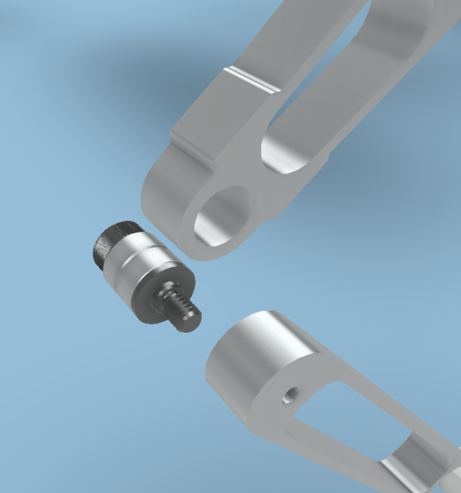
Joints
For each joint, there are two deep groove ball bearings stacked next to each other in on link, and a shoulder bolt goes through them and threads into the opposing link.
Feet
The robot feet are silicone pieces that we made using a 3D printed, 2-part mold.

Frame
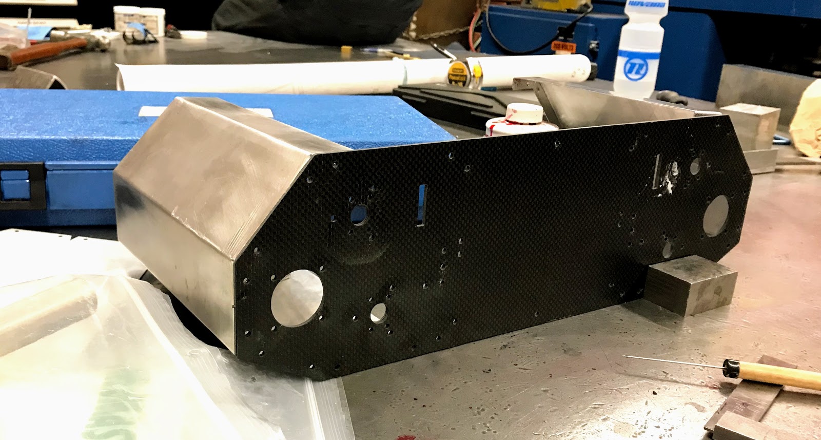
The frame of the robot is thankfully very simple. We have two waterjet, 4mm carbon fiber panels on each side, connected by two 1/32” 5052 aluminum sheet metal parts. These sheet metal parts were cut using a waterjet, and then folded up by hand (long story, but because the two carbon fiber panels are canted inwards, the tabs on the aluminum part couldn’t be folded on a brake).
Electronics
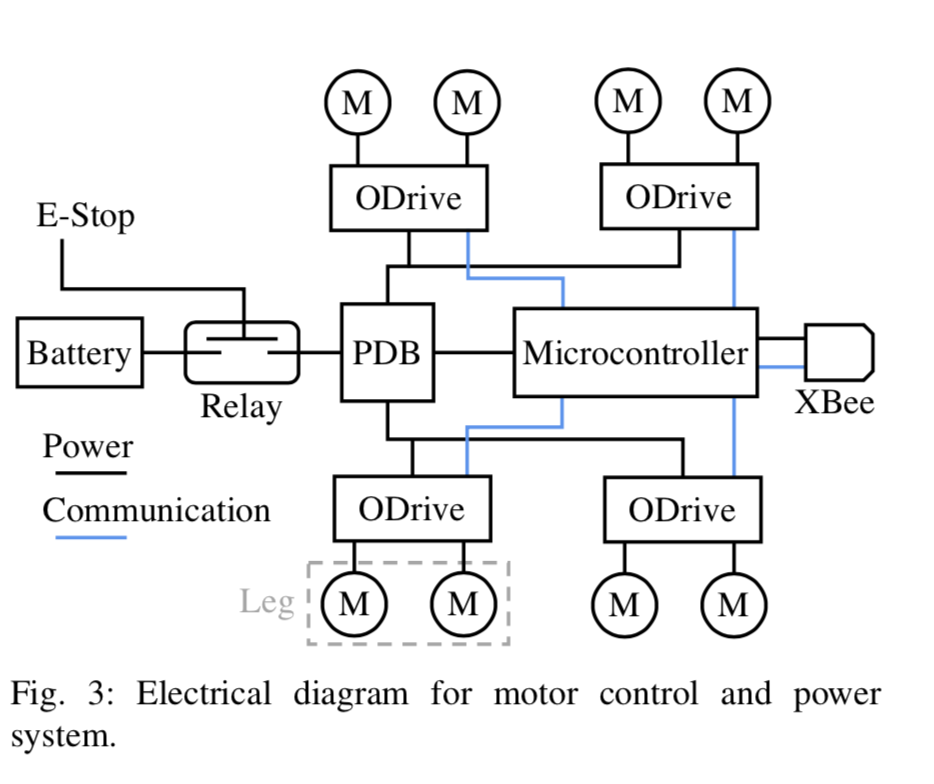
Doggo has four v3.5, 48V ODrives, two for each leg, mounted on the carbon fiber side panels. Sitting on a 2mm carbon fiber plate in the middle, we have a Teensy 3.5, a Sparkfun BNO080 IMU, and a 5mW Xbee. The Teensy talks to the ODrives over four separate UART lines, each operating at 500,000 baud. Underneath this plate, we have the power distribution board (a janky quadcopter PDB we found on Amazon), and a fancy Gigavac P105 Mini-Tactor relay so we can kill the robot power using an offboard ESTOP switch. We also put our two, 1000mah 6s Tattu lipo batteries down there.
Last, but not least, each motor has a AS5047P encoder to track the motor angle. We actually are only using the incremental interface, because at the time we built the robot, there was no absolute encoder support on the ODrive and we couldn’t make the index pin functionality work either.
Electronics schematic
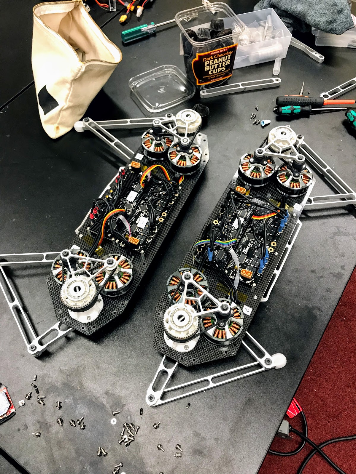
Layout of ODrives
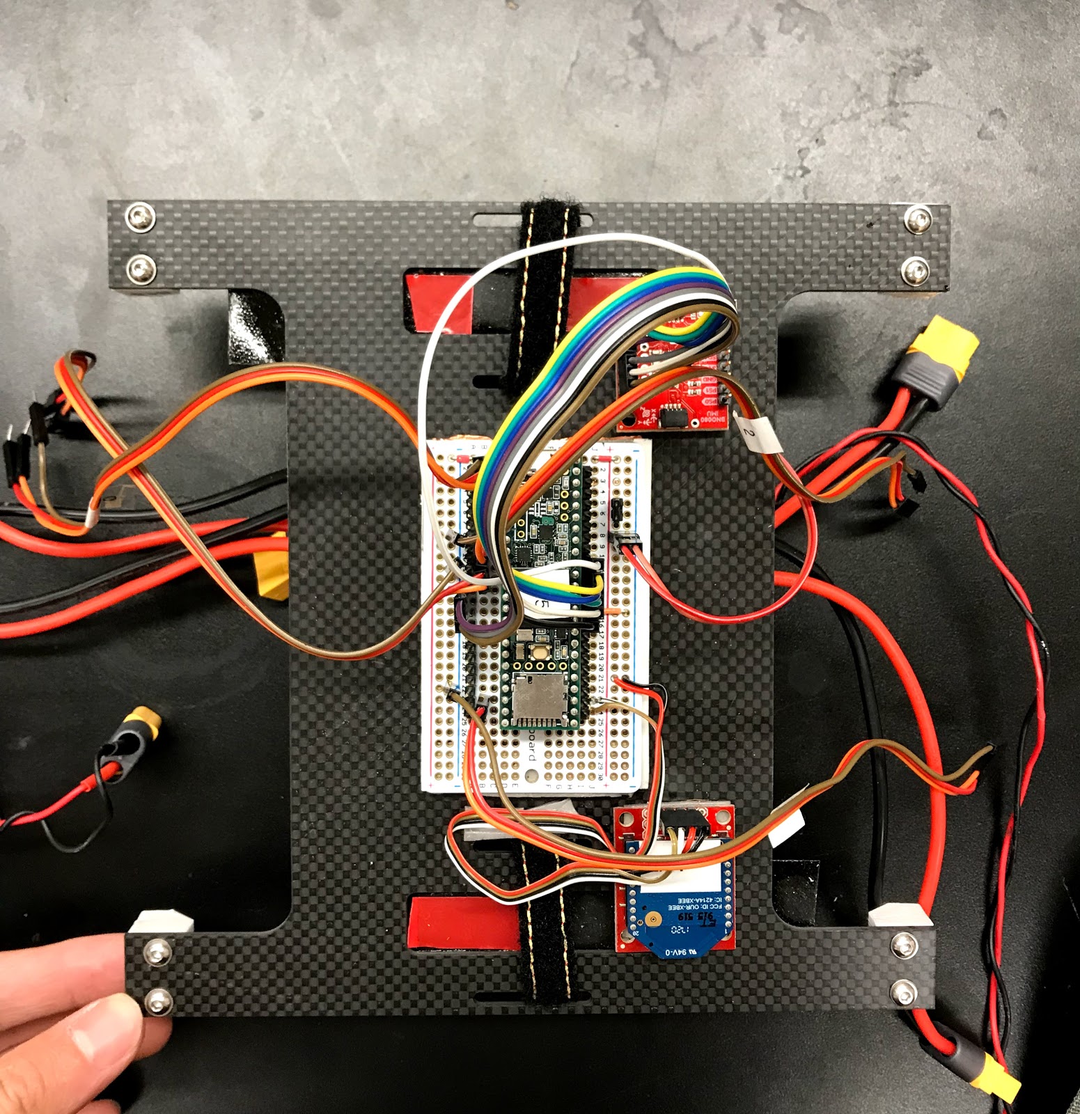
Top side of the middle electronics plate
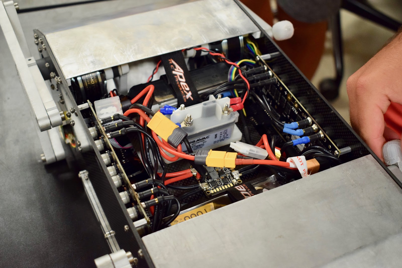
The belly of the robot: Relay (translucent piece in the middle), PDB (golden board in front of the relay), and batteries (close and far).
Software
Overview
The Doggo software is relatively simple as far as things go. The gist of it is that we have a state machine that flips between different behaviors (like trot, jump etc), and for each behavior we send different position commands and gains to the four ODrives. We also have some helper threads running, like one to take IMU measurements, another to record telemetry from the ODrives, another to take commands over Xbee, etc.
Leg trajectories
The robot walks, trots, bounds, and pronks by commanding different sinusoidal open-loop trajectories to the four ODrives. The leg trajectories are composed of two halves of sinusoidal curves for the flight and stance phases shown in orange and purple in the picture. The geometric parameters of the sinusoids, the virtual leg compliance, and the duration of time that the leg spends traversing each sinusoidal segment, were varied to create different gaits.

At any given time, the Teensy computes the desired foot locations in cartesian coordinates, and then converts them to leg angles (θ) and leg separations (γ). These two numbers describe the virtual leg that originates at the hip joint of the leg and terminates at the foot.
These virtual leg parameters (theta and gamma) and their corresponding virtual stiffness and damping coefficients are sent from the Teensy to the four ODrives at the 100Hz refresh rate. The ODrives then run a custom PD controller to generate torques in theta-gamma space. The ODrives then use the Jacobian of the leg to transform torques in theta-gamma space into torques in the motor0-motor1 space.
ODrive Control
We implemented a custom binary UART protocol to send and receive data. The binary protocol is significantly faster than the ASCII protocol, which (I think) was the only protocol implemented for the Arduino when we built the robot. If you’d like more of the specifics, visit https://github.com/Nate711/Doggo/blob/master/lib/ODriveArduino/ODriveArduino.cpp
I think that about wraps everything up! Let me know if you have questions, and I’ll also try to update the post if people are interested in more details.