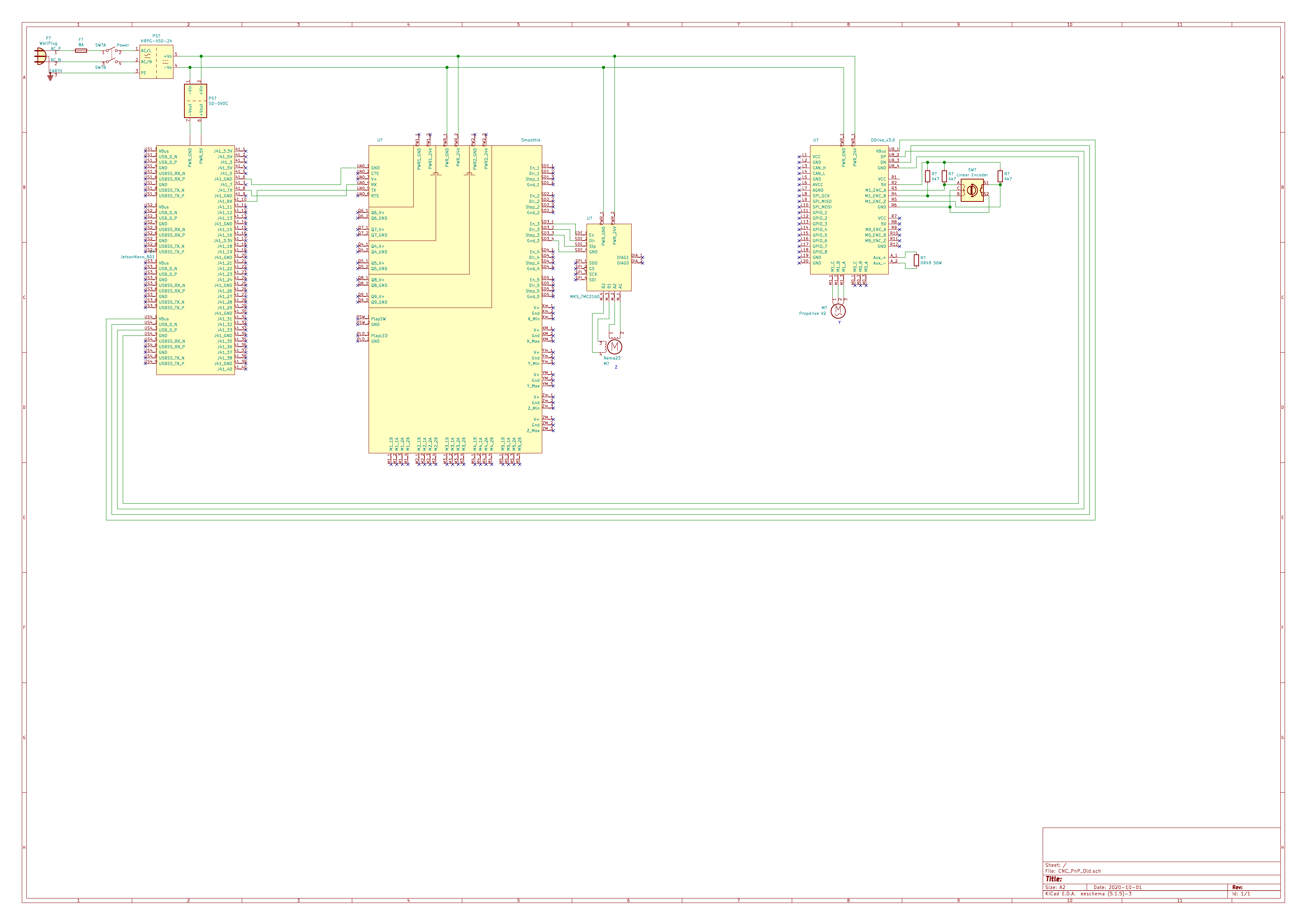
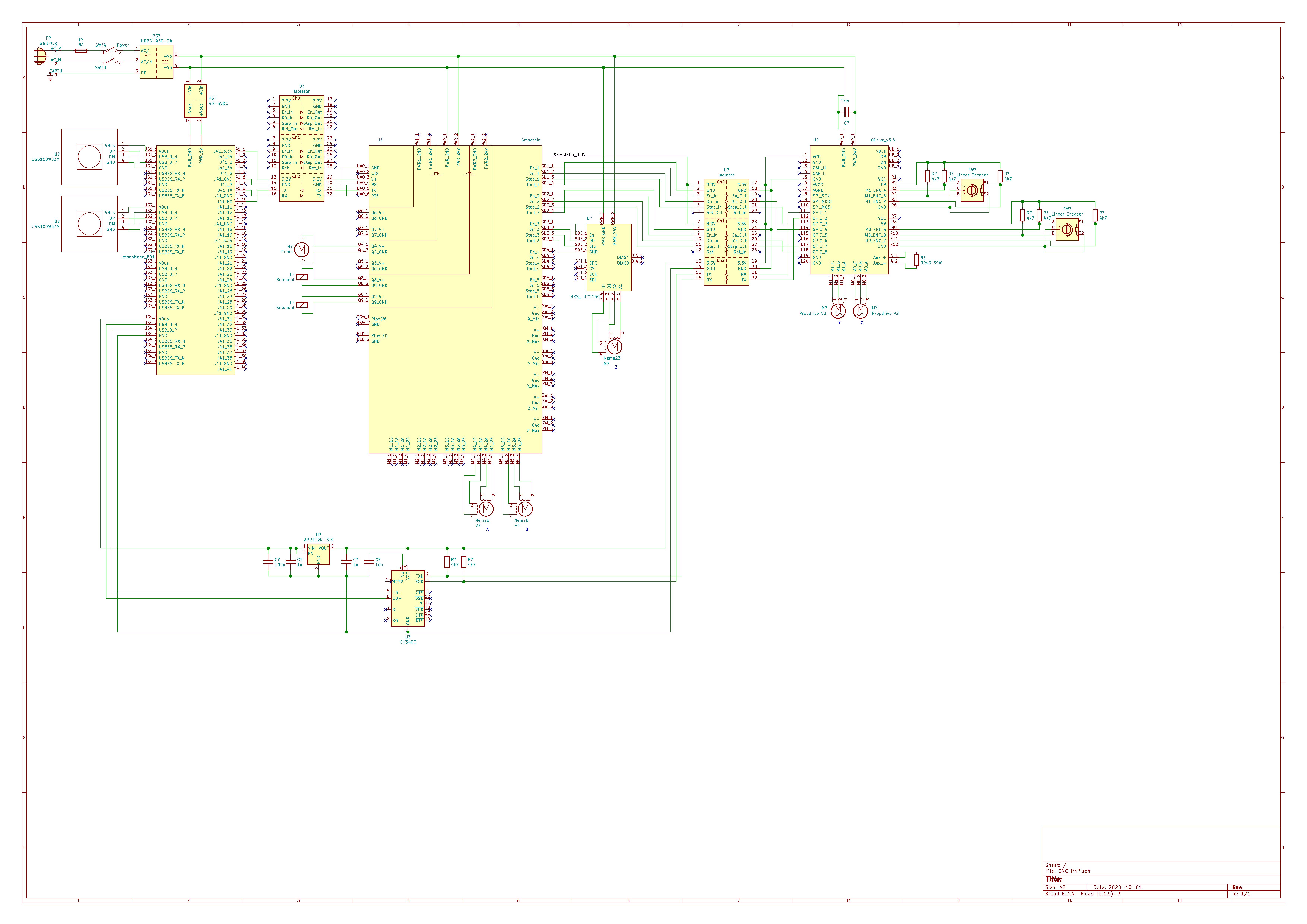
If this was caused by a ground loop through the Jetson Nano, how should I hook it up then? The final control will be 2x Step/For from the Smoothieboard and Uart from the Jetson Nano… Isolating all of those signals will be quite complicated (high speed).
I also don’t understand why the driver IC I haven’t used yet is getting warm now… It didn’t do that before.
Do you have plastic isolators between the screws/nuts & the PCB?
M0’s DRV chip supplies 5V to the circuit with a buck converter, so you probably have a short somewhere that it’s struggling with. It’s easy to end up with a ground loop that fries the STM32 if you’re using UART or step/dir and another board, unfortunately. ODrive v4 will have isolators for this reason.
Do you have plastic isolators between the screws/nuts & the PCB?
No I don’t have isolating washers. I will get some and add them.
M0’s DRV chip supplies 5V to the circuit with a buck converter, so you probably have a short somewhere that it’s struggling with. It’s easy to end up with a ground loop that fries the STM32 if you’re using UART or step/dir and another board, unfortunately. ODrive v4 will have isolators for this reason.
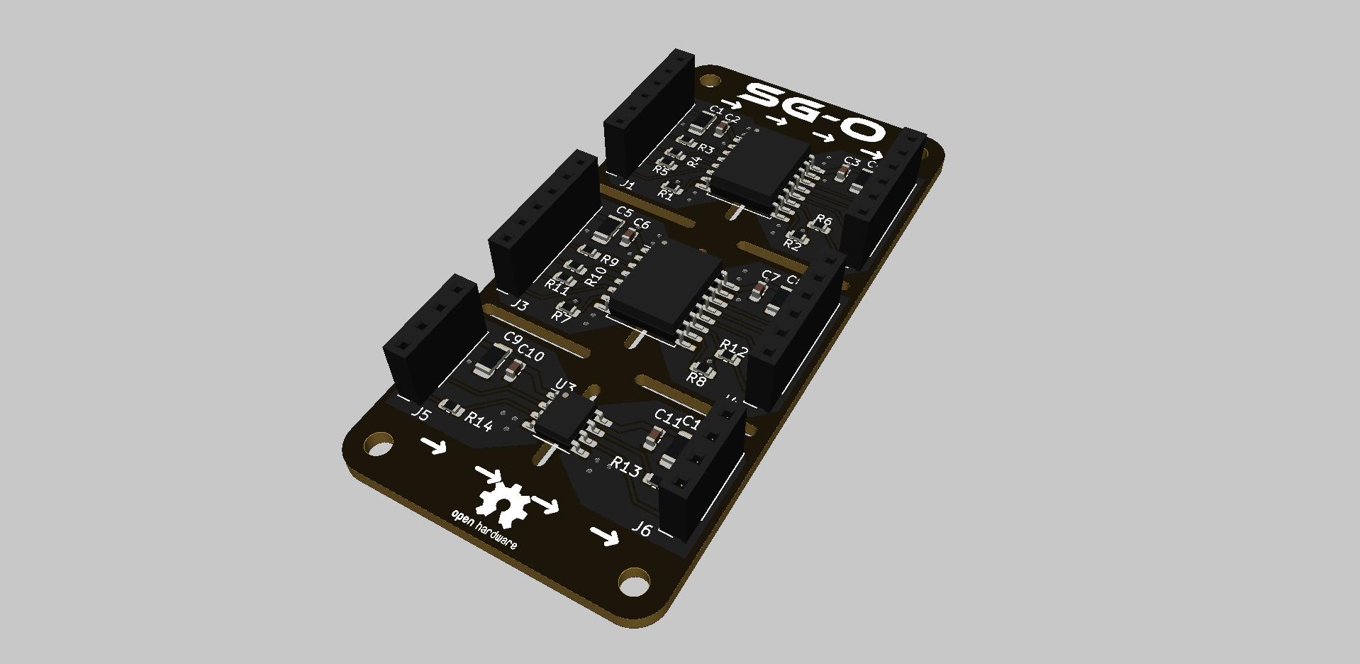
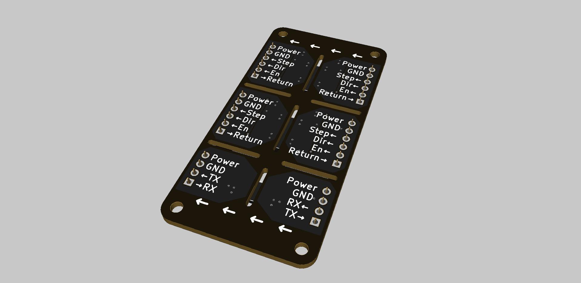
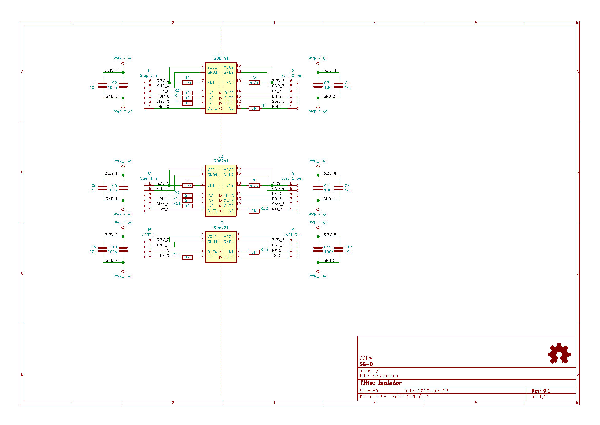
I already started designing a optical isolator board for these connections.
If I desolder the STM32 and then power up the board to check whether the M0 DRV stays cold could something misbehave? Or would this be a safe test?
Check the schematic, but I believe all the important interfaces (PWM gate drive signals, enable etc) have the appropriate pull up / pull down resistors, so they won’t be floating. It should be a safe test.
Probably, the current drawn by the blown up STM32 (causing it to get hot) is also causing the buck converter to get hot, but the DRV chip should be robust against that situation.
Ideally, get the ones with a ridge that prevents the metal screw from fouling against the inside of the hole, where it could contact one or more copper layers. Plain nylon flat washers aren’t enough.
After speaking with Oskar, he also suggested putting maybe 3k ohm resistors in series with the STM input pins that you’re using, if you don’t want to go to full isolation
It’s not easy to isolate the USB, and from what I saw it looks like that was the only ground loop connection right? The only 100% safe way to avoid ground loops is to use a dedicated power supply for motor power, and use a separate power supply for logic power. Best case the PSU is isolated from mains earth (check with multimeter for no connection between V- and PE (mains protective earth)).
I use the included plastic standoffs. This shouldn’t be a problem.
I designed an isolation board. Will put it in production tomorrow This should solve all of this.
I won’t use USB in the future. https://github.com/SG-O/Isolator
Ordered the PCBs and components. If you are interested in this you can get the design and manufacturing files from my GitHub https://github.com/SG-O/Isolator.
It is licensed under the MIT license, so no strings attached
The electrical isolation seems to do the trick. Communication over UART1 works and I am controlling M0 with Step/Dir. M1 is still untested but this shouldn’t cause any issues. Once everything is done, I’ll share it in a new thread!
I have a few of the isolator boards (unpopulated) left. I’m willing to send them to anyone interested for the manufacturing cost of the board + shipping. If you want one (I hope this is fine with the Owner :D) write me a message.
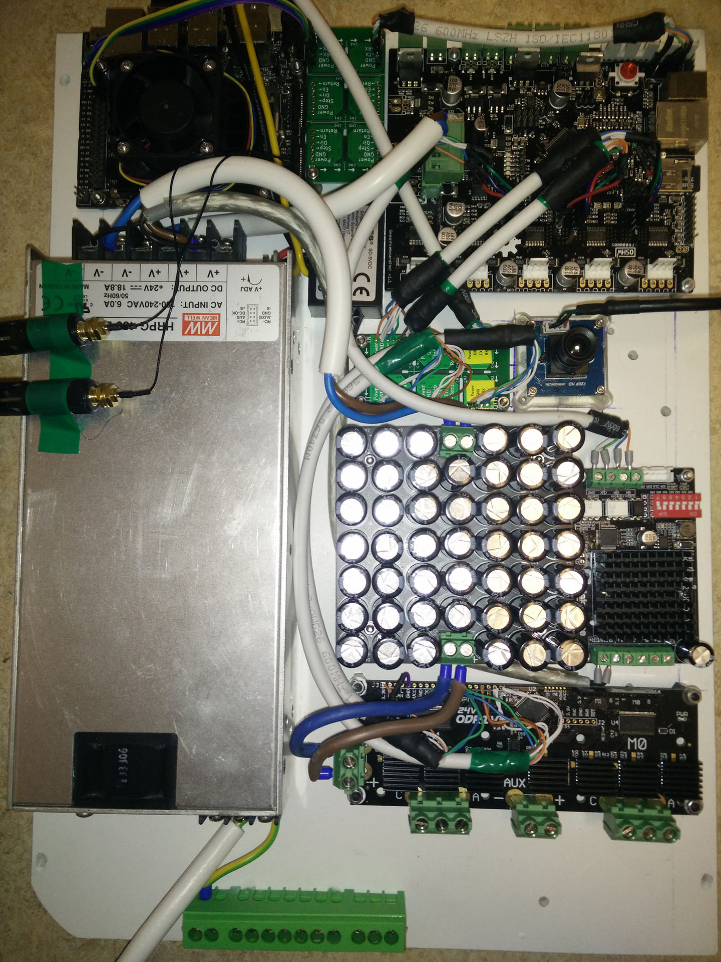
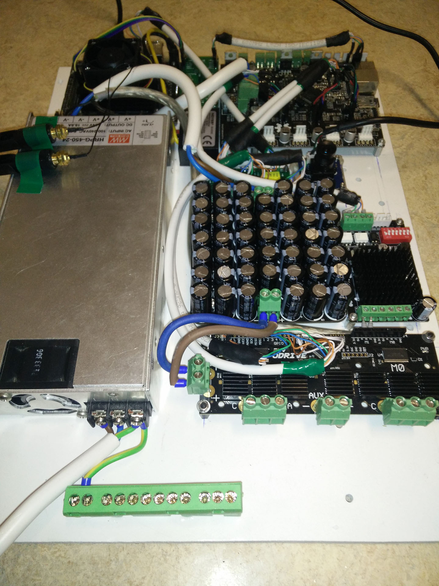
Wow, that capacitor bank…
Do you know if that is necessary? If so, how did you decide how much capacitance to add? Or was it a case of “as much as would fit”
It was a case of how much fits in 100 x 100mm with the caps being as cheap as possible while not using crap caps. The total capacitance is 47mF 50V. The total cost for it is 15$
Fair enough. Were you getting “DC Bus undervoltage” errors before? Or did you add this just because “you can never have too much DC Bus capacitance”?
Just fyi, there is such a thing as “too much capacitance” on a SMPS output. They can trip out on overload on start-up, and they can become unstable, especially with a low-ESR capacitor bank.
That said, it’s probably fine if it worked once already.
Also, you are sort of “asking for trouble” if you ever get another short-circuit. Normally, if there is a short on the DC Bus, a power supply like yours would either trip off or go into current limit. Whereas that capacitor bank will store 50 Joules, more than enough to blow a large hole in any PCB.
I simulated the whole system (especially all axis acceleration scenarios) before building and there are certain scenarios where there could be short periods of overcurrent (I have more motors than the two driven by the ODrive). The capacitor bank should smooth those out (I should only need ~10mF).
The SMPS I use has a current limiting output and won’t trip. Also there are no limits to capacitive loads according to the datasheet. So there is no issue there.
I am aware of this and accept the risks . The only other way would have been to reduce the acceleration of the X and Y axis, which would slow down my machine significantly. A bigger power supply would also have been too expensive (~200$), as I already owned this one.
I didn’t model the ODrive at all. I only modeled the constant loads as resistive loads (assuming 10W for the Jetson, 20W for the vacuum pump,…). Then I calculated the mechanical inertia for each axis, 1 kg mm² for X and 2.5 kg mm² for Y (The stepper motor based axis I assumed to be constant current loads and weren’t considered). Then I used a DC motor model (should be accurate enough) for the two ODrive axis.
Right… That’s probably why you ended up with such an oversized power supply then…
The current drawn from the DC supply is NOT the same as the current in the motor! It is significantly lower, and only starts to match the motor current when the motor at its maximum possible speed for a given voltage & load. Even in this case it is limited to 80% of the motor current, because the ODrive places a limit on PWM magnitude at 80%.
The case of accelerating from a dead stop actually draws the least amount of current for a given torque, because the speed is near zero.
Whereas a brushed DC motor does not limit the current or convert voltage, so it would apply more starting torque, and would also be much less efficient at startup due to resistive losses.
I think it would be useful to have a proper LTSpice model for ODrive, at least for torque control mode only, but I don’t know if anyone has one. Maybe Oskar might.
Even a super-simplified set of equations such as this might be useful:
inputs are torque_command and dc_bus_voltage
motor_current is proportional to torque_command
resistive_voltage_loss is proportional to motor_current
velocity is proportional to time-integral of torque_command
back_emf is proportional to velocity
pwm_duty is proportional to (back_emf + resistive_voltage_loss) / dc_bus_voltage, and saturates at 0.8, causing a simulator warning
dc_bus_current is proportional to (motor_current * pwm_duty)
Of course, this ignores the transient nature of these signals, but it would be a better approximator of DC Bus current than a brushed motor model.
Thanks for your detailed post! I see how I messed my simulation attempts up. You are absolutely correct, a simple DC motor model can’t simulate the ODrive. Having an accurate model would be awesome, but creating it would be a lot of work.
 This should solve all of this.